MX25L12835F
9-19. Fast Boot
The Fast Boot Feature provides the ability to automatically execute read operation after power on cycle or reset
without any read instruction.
A Fast Boot Register is provided on this device. It can enable the Fast Boot function and also define the number of
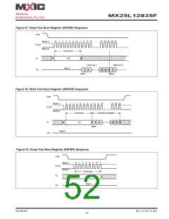
delay cycles and start address (where boot code being transferred). Instruction WRFBR (write fast boot register) and
ESFBR (erase fast boot register) can be used for the status configuration or alternation of the Fast Boot Register
bit. RDFBR (read fast boot register) can be used to verify the program state of the Fast Boot Register. The default
number of delay cycles is 12 cycles (11h), and there is a 8bytes boundary address for the start of boot code access.
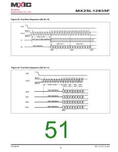
When CS# starts to go low, data begins to output from default address after the delay cycles (default as 12 cycles).
After CS# returns to go high, the device will go back to standard SPI mode. In the fast boot data out process from
CS# goes low to CS# goes high, a minimum of one byte must be output.
Once Fast Boot feature has been enabled, the device will automatically start a read operation after power on cycle,
reset command, or hardware reset operation.
The fast Boot feature can support Single I/O and Quad I/O interface. If the QE bit of Status Register is “0”, the data
is output by Single I/O interface. If the QE bit of Status Register is set to “1”, the data is output by Quad I/O interface.
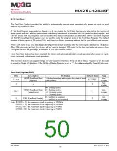
Fast Boot Register (FBR)
Bits
Description
FBSA (FastBoot Start
Address)
Bit Status
16 bytes boundary address for the start of boot
code access.
Default State
Type
Non-
Volatile
31 to 4
FFFFFFF
Non-
Volatile
3
2 to 1
0
x
1
11
1
00: 6 delay cycles
01: 8 delay cycles
10: 10 delay cycles
11: 12 delay cycles
0=FastBoot is enabled.
1=FastBoot is not enabled.
FBSD (FastBoot Start
Delay Cycle)
Non-
Volatile
Non-
Volatile
FBE (FastBoot Enable)
Note: If FBSD = 11, the maximum clock frequency is 133 MHz
If FBSD = 10, the maximum clock frequency is 104 MHz
If FBSD = 01, the maximum clock frequency is 84 MHz
If FBSD = 00, the maximum clock frequency is 70 MHz
P/N: PM1795
REV. 1.0, OCT. 23, 2012
50

 Macronix [ MACRONIX INTERNATIONAL ]