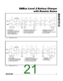
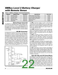
SMBus Level 2 Battery Charger
with Remote Sense
C
is also much lower impedance than R near
GM
= 5A/V
OUT
OUT
L
crossover so the parallel impedance is mostly capaci-
C
OUT
OSC
= 2 x 10µF
= 400kHz
tive and:
F
R ⋅
1
R = 0.2Ω
F = 50kHz
CO_CV
L
L
≅
(1+sC
×R ) sC
OUT
L
OUT
To ensure that the compensation zero adequately can-
If R
is small enough, its associated output zero has
ESR
cels the output pole, select f
≤ f
:
Z_CV
P_OUT
a negligible effect near crossover and the loop-transfer
function can be simplified as follows:
C
≥ (R / R ) C
L CV
CV
OUT
R
CV
LTF = GM
×
G
MV
OUT
sC
OUT
C
≥ 400pF (assuming 2 cells and 2A maximum
CV
charge current.)
Setting LTF = 1 to solve for the unity-gain frequency
yields:
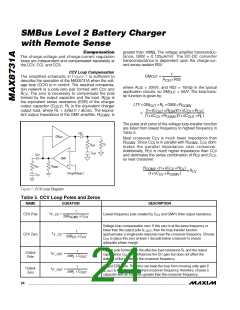
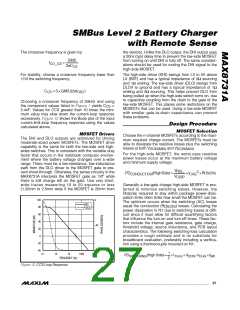
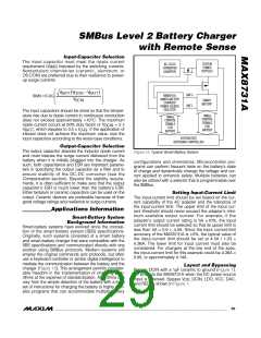
Figure 8 shows the Bode plot of the voltage-loop fre-
quency response using the values calculated above.
R
CV
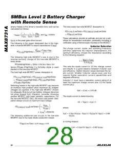
CCI Loop Compensation
The simplified schematic in Figure 9 is sufficient to
describe the operation of the MAX8731A when the bat-
tery current loop (CCI) is in control. Since the output
capacitor’s impedance has little effect on the response
of the current loop, only a simple single pole is required
f
= GM
×G
×
CO_CV
OUT
MV
2π ×C
OUT
For stability, choose a crossover frequency lower than
1/10 the switching frequency. For example, choose a
crossover frequency of 50kHz and solve for R
the component values listed in Figure 1 to yield R
using
CV
VC
=
to compensate this loop. A
is the internal gain of the
CSI
10kΩ:
current-sense amplifier. RS2 is the charge current-
sense resistor (10mΩ). R
is the equivalent output
OGMI
impedance of the GMI amplifier, which is greater than
2π ×C
× f
OUT CO_CV
R
=
≅10kΩ
10MΩ. GMI is the charge-current amplifier transcon-
ductance = 1µA/mV. GM
transconductance = 5A/V.
CV
GMV ×GM
OUT
is the DC-DC converter
OUT
GMV = 0.125µA/mV
80
60
40
20
0
0
CSIP
CSIN
GM
OUT
RS2
CSI
-45
-90
CCI
GMI
-20
-40
MAG
PHASE
C
R
OGMI
CI
-135
0.1
1
10 100 1k
FREQUENCY (Hz)
10k 100k 1M
ChargeCurrent( )
Figure 8. CCV Loop Response
Figure 9. CCI Loop Diagram
______________________________________________________________________________________ 25

 MAXIM [ MAXIM INTEGRATED PRODUCTS ]