SMBus Level 2 Battery Charger
with Remote Sense
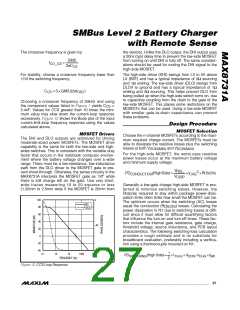
where t
is the driver’s transition time and can be
The total power low-side MOSFET dissipation is:
TRANS
calculated as follows:
PD
(LowSide) ≈PD
(LowSide)
TOTAL
CONDUCTION
⎛
⎞
1
1
2Q
G
+ PD
(LowSide)
BDY
t
=
+
×
, and f
≈ 400kHz
TRANS
SW
⎜
⎟
I
I
I
⎝
⎠
Gsrc
Gsnk
GATE
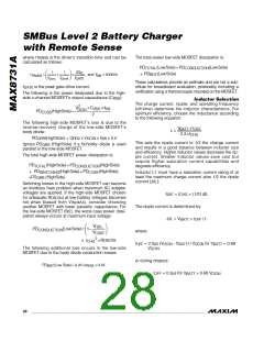
These calculations provide an estimate and are not a sub-
stitute for breadboard evaluation, preferably including a
verification using a thermocouple mounted on the MOSFET.
I
is the peak gate-drive current.
GATE
The following is the power dissipated due to the high-
side n-channel MOSFET’s output capacitance (C
):
RSS
Inductor Selection
The charge current, ripple, and operating frequency
(off-time) determine the inductor characteristics. For
optimum efficiency, choose the inductance according
to the following equation:
2
V
×C
× f
RSS SW
DCIN
PD
(HighSide) ≈
COSS
2
The following high-side MOSFET’s loss is due to the
reverse-recovery charge of the low-side MOSFET’s
body diode:
V
× t
BATT OFF
L =
0.3×I
CHG
PD
(HighSide) = Q
x V
x f
x 0.5
SW
QRR
RR2
DCIN
This sets the ripple current to 1/3 the charge current
and results in a good balance between inductor size
and efficiency. Higher inductor values decrease the rip-
ple current. Smaller inductor values save cost but
require higher saturation current capabilities and
degrade efficiency.
Ignore PD
(HighSide) if a Schottky diode is used
QRR
parallel to the low-side MOSFET.
The total high-side MOSFET power dissipation is:
PD
(HighSide) ≈ PD
(HighSide)
TOTAL
CONDUCTION
+ PD
(HighSide) +PD
(HighSide)
(HighSide)
SWITCHING
COSS
Inductor L1 must have a saturation current rating of at
least the maximum charge current plus 1/2 the ripple
current (ΔIL):
+PD
QRR
Switching losses in the high-side MOSFET can become
an insidious heat problem when maximum AC adapter
voltages are applied. If the high-side MOSFET chosen
for adequate R
hot when biased from V
I
= I
+ (1/2) ΔIL
CHG
SAT
at low-battery voltages becomes
DS(ON)
, consider choosing
IN(MAX)
The ripple current is determined by:
ΔIL = V × t
another MOSFET with lower parasitic capacitance. For
the low-side MOSFET (N2), the worst-case power dissi-
pation always occurs at maximum input voltage:
/ L
OFF
BATT
V
⎛
⎞
FBS_
PD
(LowSide) = 1−
CONDUCTION
⎜
⎟
where:
V
⎝
⎠
CSSP
2
× I
×RDS(ON)
CHG
t
= 2.5µs (V
- V
) / V
for V
< 0.88
OFF
DCIN
BATT
DCIN
BATT
The following additional loss occurs in the low-side
MOSFET due to the body diode conduction losses:
V
DCIN
or during dropout:
= 0.3µs for V
PD
(Low Side) = 0.05×I
× 0.4V
BDY
PEAK
t
> 0.88 V
OFF
BATT
DCIN
28 ______________________________________________________________________________________

 MAXIM [ MAXIM INTEGRATED PRODUCTS ]