SMBus Level 2 Battery Charger
with Remote Sense
Input-Capacitor Selection
The input capacitor must meet the ripple current
SYSTEM
POWER
AC-TO-DC
CONVERTER
(ADAPTER)
requirement (I
) imposed by the switching currents.
RMS
Nontantalum chemistries (ceramic, aluminum, or
OS-CON) are preferred due to their resilience to power-
up surge currents:
SUPPLIES
⎛
⎜
⎞
⎟
V
V
− V
(
)
BATT DCIN BATT
BATT+
BATT-
MAX8731A
SMART-BATTERY
CHARGER/
POWER-SOURCE
SELECTOR
IRMS =ICHG
⎜
⎝
⎟
⎠
V
DCIN
SMART
BATTERY
The input capacitors should be sized so that the temper-
ature rise due to ripple current in continuous conduction
does not exceed approximately +10°C. The maximum
SMBus
CONTROL
SIGNALS
FOR
SMBus
CONTROL
SIGNALS
FOR
ripple current occurs at 50% duty factor or V
= 2 x
DCIN
V
, which equates to 0.5 x I
. If the application of
BATT
CHG
BATTERY
BATTERY
interest does not achieve the maximum value, size the
SYSTEM HOST
(KEYBOARD CONTROLLER)
input capacitors according to the worst-case conditions.
Output-Capacitor Selection
The output capacitor absorbs the inductor ripple current
and must tolerate the surge current delivered from the
battery when it is initially plugged into the charger. As
such, both capacitance and ESR are important parame-
ters in specifying the output capacitor as a filter and to
ensure stability of the DC-DC converter (see the
Compensation section). Beyond the stability require-
ments, it is often sufficient to make sure that the output
capacitor’s ESR is much lower than the battery’s ESR.
Either tantalum or ceramic capacitors can be used on the
output. Ceramic devices are preferable because of their
good voltage ratings and resilience to surge currents.
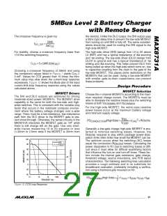
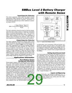
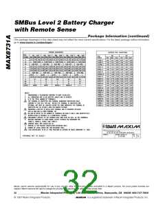
Figure 13. Typical Smart-Battery System
configurations and chemistries. Microcontroller pro-
grams can perform frequent tests on the battery’s state
of charge and dynamically change the voltage and cur-
rent applied to enhance safety. Multiple batteries can
also be utilized with a selector that is programmable over
the SMBus.
Setting Input-Current Limit
The input-current limit should be set based on the cur-
rent capability of the AC adapter and the tolerance of
the input-current limit. The upper limit of the input cur-
rent threshold should never exceed the adapter’s mini-
mum available output current. For example, if the
adapter’s output current rating is 5A 10%, the input
current limit should be selected so that its upper limit is
less than 5A × 0.9 = 4.5A. Since the input current-limit
accuracy of the MAX8731A is 3%, the typical value of
the input-current limit should be set at 4.5A / 1.03 ≈
4.36A. The lower limit for input current must also be
considered. For chargers at the low end of the spec,
the input-current limit for this example could be 4.36A ×
0.95, or approximately 4.14A.
Applications Information
Smart-Battery System
Background Information
Smart-battery systems have evolved since the concep-
tion of the smart-battery system (SBS) specifications.
Originally, such systems consisted of a smart battery
and smart-battery charger that were compatible with the
SBS specifications and communicated directly with one
another using SMBus protocols. Modern systems still
employ the original commands and protocols, but often
use a keyboard controller or similar digital intelligence to
mediate the communication between the battery and the
charger (Figure 13). This arrangement permits consider-
able freedom in the implementation of charging algo-
rithms at the expense of standardization. Algorithms can
vary from the simple detection of the battery with a fixed
set of instructions for charging the battery to highly com-
plex programs that can accommodate multiple battery
Layout and Bypassing
Bypass DCIN with a 1µF ceramic to ground (Figure 1).
D1 protects the MAX8731A when the DC power source
input is reversed. Bypass V , DCIN, LDO, VCC, DAC,
DD
and REF as shown in Figure 1.
______________________________________________________________________________________ 29

 MAXIM [ MAXIM INTEGRATED PRODUCTS ]