SMBus Level 2 Battery Charger
with Remote Sense
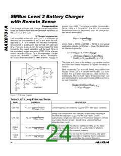
control point. Clamping the other two control loops
IMIN must be high, IMAX must be low, and OVP must
be low for the controller to initiate a new cycle. If the
peak inductor current exceeds the IMAX comparator
threshold or the output voltage exceeds the OVP
threshold, then the on-time is terminated. The cycle-by-
cycle current limit effectively protects against overcur-
rent and short-circuit faults.
close to the lowest control loop ensures fast transition
with minimal overshoot when switching between differ-
ent control loops (see the Compensation section).
Continuous-Conduction Mode
With sufficient charge current, the MAX8731A’s induc-
tor current never crosses zero, which is defined as con-
tinuous-conduction mode. The regulator switches at
If during the off-time the inductor current goes to zero,
the ZCMP comparator output pulls high, turning off the
low-side MOSFET. Both the high- and low-side
MOSFETs are turned off until another cycle is ready to
begin. ZCOMP causes the MAX8731A to enter into dis-
continuous-conduction mode (see the Discontinuous
Conduction section).
400kHz (nominal) if V
< 0.88 x V
. The con-
CSSP
CSIN
troller starts a new cycle by turning on the high-side
MOSFET and turning off the low-side MOSFET. When
the charge-current feedback signal (CSI) is greater
than the control point (LVC), the CCMP comparator out-
put goes high and the controller initiates the off-time by
turning off the high-side MOSFET and turning on the
low-side MOSFET. The operating frequency is gov-
There is a 0.3µs minimum off-time when the (V
-
CSSP
≥ 0.88 x
V
V
) differential becomes too small. If V
CSIN
CSSP
CSIN
, the threshold for the 0.3µs minimum off-time is
erned by the off-time and is dependent upon V
CSSP
and
CSIN
reached. The switching frequency in this mode varies
according to the equation:
V
. The off-time is set by the following equation:
V
− V
CSIN
CSSP
1
t
= 2.5μs ×
OFF
f =
V
CSSP
L ×I
RIPPLE
− V
CSSN BATT
+ 0.3μs
V
The on-time can be determined using the following
equation:
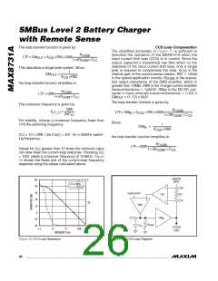
Discontinuous Conduction
The MAX8731A can also operate in discontinuous-con-
duction mode to ensure that the inductor current is
always positive. The MAX8731A enters discontinuous-
conduction mode when the output of the LVC control
point falls below 100mV. This corresponds to peak
inductor current = 500mA:
L ×I
RIPPLE
t
=
ON
V
− V
CSSN
BATT
where:
V
× t
BATT OFF
L
I
=
RIPPLE
100mV
1
The switching frequency can then be calculated:
I
=
×
= 250mA
CHG
2
20×RS2
1
f
=
SW
charge current for RS2 = 10mΩ.
t
+ t
ON OFF
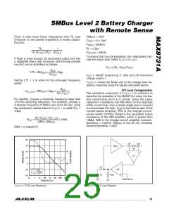
In discontinuous mode, a new cycle is not started until
the LVC voltage rises above 100mV. Discontinuous-
mode operation can occur during conditioning charge
of overdischarged battery packs, when the charge cur-
rent has been reduced sufficiently by the CCS control
loop, or when the charger is in constant-voltage mode
with a nearly full battery pack.
These equations describe the controller’s pseudo-
fixed-frequency performance over the most common
operating conditions.
At the end of the fixed off-time, the controller initiates a
new cycle if the control point (LVC) is greater than
100mV and the peak charge current is less than the
cycle-by-cycle current limit. Restated another way,
______________________________________________________________________________________ 23

 MAXIM [ MAXIM INTEGRATED PRODUCTS ]