SMBus Level 2 Battery Charger
with Remote Sense
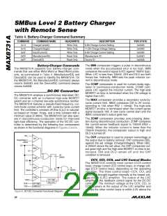
Table 4. Battery-Charger Command Summary
COMMAND
COMMAND NAME
ChargeCurrent()
ChargeVoltage()
InputCurrent()
READ/WRITE
Write Only
Write Only
Write Only
Read Only
Read Only
DESCRIPTION
6-Bit Charge-Current Setting
11-Bit Charge-Voltage Setting
6-Bit Charge-Current Setting
Manufacturer ID
POR STATE
0x0000
0x14
0x15
0x0000
0x3F
0x0080
0xFE
ManufacturerID()
DeviceID()
0x004D
0x0008
0xFF
Device ID
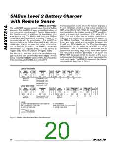
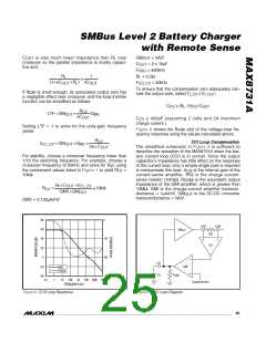
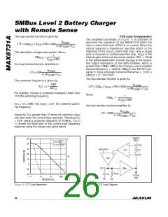
The IMIN comparator triggers a pulse in discontinuous
mode when the accumulated error is too high. IMIN
compares the control signal (LVC) against 100mV (typ).
When LVC is less than 100mV, DHI and DLO are both
forced low. Indirectly, IMIN sets the peak inductor cur-
rent in discontinuous mode.
Battery-Charger Commands
The MAX8731A supports four battery-charger com-
mands that use either Write-Word or Read-Word proto-
cols, as summarized in Table 4. ManufacturerID() and
DeviceID() can be used to identify the MAX8731A. On
the MAX8731A, the ManufacturerID() command always
returns 0x004D and the DeviceID() command always
returns 0x0008.
The CCMP comparator is used for current-mode regu-
lation in continuous-conduction mode. CCMP com-
pares LVC against the inductor current. The high-side
MOSFET on-time is terminated when the CSI voltage is
higher than LVC.
DC-DC Converter
The MAX8731A employs a synchronous step-down DC-
DC converter with an n-channel high-side MOSFET
switch and an n-channel low-side synchronous rectifier.
The MAX8731A features a pseudo-fixed-frequency, cur-
rent-mode control scheme with cycle-by-cycle current
The IMAX comparator provides a secondary cycle-by-
cycle current limit. IMAX compares CSI to 2V (corre-
sponding to 10A when RS2 = 10mΩ). The high-side
MOSFET on-time is terminated when the current-sense
signal exceeds 10A. A new cycle cannot start until the
IMAX comparator’s output goes low.
limit. The controller’s constant off-time (t
) is calculat-
OFF
ed based on V
, V
, and a time constant with a
CSSP CSIN
minimum value of 300ns. The MAX8731A can also oper-
ate in discontinuous-conduction mode for improved
light-load efficiency. The operation of the DC-DC con-
troller is determined by the following four comparators
as shown in the functional diagrams in Figures 2 and 6:
The ZCMP comparator provides zero-crossing detec-
tion during discontinuous conduction. ZCMP compares
the current-sense feedback signal to 750mA (RS2 =
10mΩ). When the inductor current is lower than the
750mA threshold, the comparator output is high and
DLO is turned off.
FBS_
The OVP comparator is used to prevent overvoltage at
the output due to battery removal. OVP compares FBS_
against the set voltage (ChargeVoltage()). When FBS_
is 200mV above the set value, the OVP comparator out-
put goes high and the high-side MOSFET on-time is ter-
minated. DHI and DLO remain off until the OVP
condition is removed.
OVP
ChargeVoltage ( )
+200mV
CSI
IMAX
2V
DH
DRIVER
R
S
Q
Q
CCMP
IMIN
CCV, CCI, CCS, and LVC Control Blocks
The MAX8731A controls input current (CCS control
loop), charge current (CCI control loop), or charge volt-
age (CCV control loop), depending on the operating
condition. The three control loops—CCV, CCI, and
CCS—are brought together internally at the lowest volt-
age-clamp (LVC) amplifier. The output of the LVC
amplifier is the feedback control signal for the DC-DC
controller. The minimum voltage at the CCV, CCI, or
CCS appears at the output of the LVC amplifier and
clamps the other control loops to within 0.3V above the
LVC
DL
DRIVER
100mV
150mV
ZCMP
OFF-TIME
ONE-SHOT
DCIN
CSIN
OFF-TIME
COMPUTE
Figure 6. DC-DC Converter Functional Diagram
22 ______________________________________________________________________________________

 MAXIM [ MAXIM INTEGRATED PRODUCTS ]