5 V/1 2 V/1 5 V o r Ad ju s t a b le , High-Effic ie nc y,
Low I , Ste p-Up DC-DC Controlle rs
Q
I
C(PEAK)
L
MAX770
MAX771
MAX772
MAX773
I
B
R
BASE
NPN
EXTH
EXTL
CS
EXT
CS
N
R
SENSE
R
SENSE
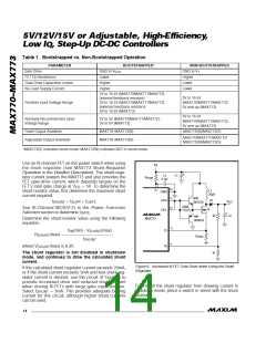
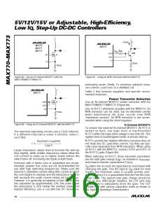
Figure 8a. Use an N-Channel MOSFET with the
MAX770/MAX771/MAX772
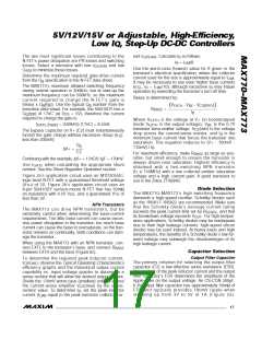
Figure 8c. Using an NPN Transistor with the MAX773
0–MAX73
preferably under 20mΩ. To minimize radiated noise,
use a toroid, a pot core, or a shielded coil.
L
Table 2 lists inductor suppliers and specific recom-
mended inductors.
MAX773
P o w e r Tra n s is t o r S e le c t io n
Use an N-channel MOSFET power transistor with the
MAX770/MAX771/MAX772 (Figure 8a).
N
EXTH
EXTL
CS
Use an N-FET whenever possible with the MAX773. An
NPN transistor can be used, but be extremely careful
whe n d e te rmining the b a s e c urre nt (s e e NPN
Transistors section). An NPN transistor is not recom-
mended when using the shunt regulator.
R
SENSE
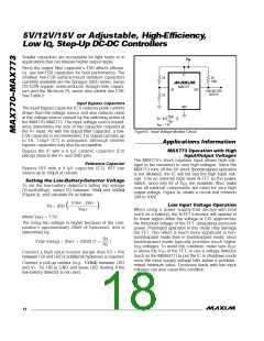
Figure 8b. Using an N-Channel MOSFET with the MAX773
N-Channel MOSFETs
To ensure the external N-channel MOSFET (N-FET) is
turne d on ha rd , us e log ic -le ve l or low-thre s hold
N-FETs when the input drive voltage is less than 8V. This
applies even in bootstrapped mode, to ensure start-up.
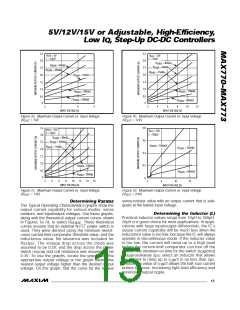
The standard operating circuits use a 22µH inductor.
If a d iffe re nt ind uc ta nc e va lue is d e s ire d , s e le c t L
such that:
N-FETs provide the highest efficiency because they do
not draw any DC gate-drive current, but they are typi-
cally more expensive than NPN transistors. When using
an N-FET with the MAX773, connect EXTH and EXTL to
the N-FET’s gate (Figure 8b).
V (max) x t (min)
IN
ON
L ≥ ——————————
/2
I
LIM
Larger inductance values tend to increase the start-up
time slightly, while smaller inductance values allow the
c oil c urre nt to ra mp up to hig he r le ve ls b e fore the
switch turns off, increasing the ripple at light loads.
When selecting an N-FET, three important parameters
are the total gate charge (Q ), on resistance (r
),
g
DS(ON)
and reverse transfer capacitance (C
).
RSS
Inductors with a ferrite core or equivalent are recom-
mended; powder iron cores are not recommended for
use with high switching frequencies. Make sure the
inductor’s saturation current rating (the current at which
the core begins to saturate and the inductance starts to
Q
takes into account all capacitances associated with
g
charging the gate. Use the typical Q value for best
g
results; the maximum value is usually grossly over-
specified since it is a guaranteed limit and not the mea-
sured value. The typical total gate charge should be
50nC or less. With larger numbers, the EXT pins may
not b e a ble to a de qua te ly drive the ga te . The EXT
rise/fall time with various capacitive loads as shown in
the Typical Operating Characteristics.
fall) exceeds the peak current rating set by R
.
SENSE
However, it is generally acceptable to bias the inductor
into saturation by approximately 20% (the point where
the inductance is 20% below the nominal value). For
highest efficiency, use a coil with low DC resistance,
______________________________________________________________________________________
16

 MAXIM [ MAXIM INTEGRATED PRODUCTS ]