5 V/1 2 V/1 5 V o r Ad ju s t a b le , High-Effic ie nc y,
Low I , Ste p-Up DC-DC Controlle rs
Q
V
= 24V TO 28V
IN
V
IN
L1
250µH
C1
47µF
R
3k
SHUNT
D1
MUR115
R
SHUNT
V
= 100V
@ 10mA
OUT
3
C2
0.1µF
MAX773
v+
10
4
SGND
LBO
N
13
12
EXTH
Si9420DY
3
V+
C4
EXTL
CS
100µF
11
8
REF
C2
0.1µF
6V (typ)
R
1.0Ω
C3
0.1µF
SENSE
14
1
V15
V12
V5
MAX773
5
LBI
2
6
10 SGND
R2
732k (1%)
7
0–MAX73
FB
SHDN
V
- V
IN (MIN) SHUNT (MAX)
R1
11.3k (1%)
R
SHUNT =
GND
9
I
SHUNT *
V
OUT
*
SEE TEXT FOR I
CALCULATION
SHUNT
R2 = (R1)
-1
)
(
V
= 1.5V
REF
V
REF
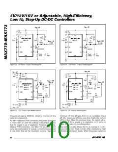
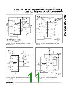
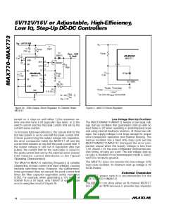
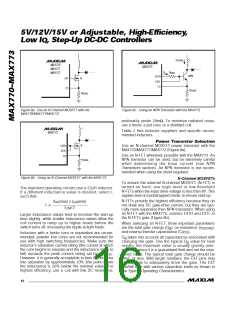
Figure 3e. 100V Output, Shunt Regulator, N-Channel Power
MOSFET
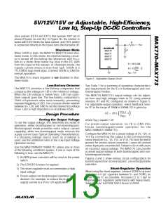
Figure 4. MAX773 Shunt Regulator
turned on, it stays on until either 1) the maximum on-
time one-shot turns it off (typically 16µs later), or 2) the
switch current reaches the peak current limit set by the
current-sense resistor.
Low-Voltage Start-Up Oscillator
The MAX770/MAX771/MAX772 feature a low input volt-
age start-up oscillator that guarantees start-up with no
load down to 2V when operating in bootstrapped mode
and using internal feedback resistors. At these low volt-
ages, the supply voltage is not large enough for proper
error-comparator operation and internal biasing. The
start-up oscillator has a fixed 50% duty cycle and the
MAX770/MAX771/MAX772 disregard the error-com-
parator output when the supply voltage is less than
2.5V. Above 2.5V, the error-comparator and normal one-
shot timing circuitry are used. The low voltage start-up
circuitry is disabled if non-bootstrapped mode is select-
ed (FB is not tied to ground).
To increase light-load efficiency, the current limit for the
first two pulses is set to one-half the peak current limit.
If those pulses bring the output voltage into regulation,
the error comparator holds the MOSFET off and the
current limit remains at one-half the peak current limit. If
the output voltage is still out of regulation after two
pulses, the current limit for the next pulse is raised to
the peak current limit set by the external sense resistor
(s e e ind uc tor c urre nt wa ve forms in the Typ ic a l
Operating Characteristics).
The MAX773 does not provide the low-voltage 50%
duty-cycle oscillator. Its minimum start-up voltage is 3V
for all modes.
The MAX770–MAX773 switching frequency is variable
(depending on load current and input voltage), causing
variable switching noise. However, the subharmonic
noise generated does not exceed the peak current limit
times the filter capacitor equivalent series resistance
(ESR). For example, when generating a 12V output at
500mA from a 5V input, only 180mV of output ripple
occurs using the circuit of Figure 2b.
Ex t e rn a l Tra n s is t o r
An N-FET p owe r s witc h is re c omme nd e d for the
MAX770/MAX771/MAX772.
The MAX773 can drive either an N-channel MOSFET
(N-FET) or an NPN because it provides two separate
______________________________________________________________________________________
12

 MAXIM [ MAXIM INTEGRATED PRODUCTS ]