MAX31865
RTD-to-Digital Converter
Detailed Description
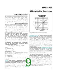
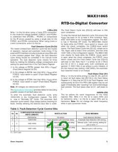
PT100 RTD RESISTANCE
vs. TEMPERATURE
The MAX31865 is a sophisticated RTD-to-digital converter
with a built-in 15-bit analog-to-digital converter (ADC),
input protection, a digital controller, an SPI-compatible
interface, and associated control logic. The signal
conditioning circuitry is optimized to worꢀ with PT100
through PT1000 RTDs. Thermistors are also supported.
450
400
350
STRAIGHT-LINE
APPROXIMATION
300
250
200
Temperature Conversion
Resistance temperature detectors (RTDs) are sensors
whose resistance varies with temperature. Platinum
is the most common, most accurate wire material;
platinum RTDs are referred to as PT-RTDs. Nicꢀel,
copper, and other metals may also be used to maꢀe
RTDs. Characteristics of platinum RTDs include a wide
temperature range (to over +800NC), excellent accuracy
and repeatability, and reasonable linearity.
RTD RESISTANCE
150
100
50
0
-200 -100
0
100 200 300 400 500 600 700
TEMPERATURE (°C)
Figure 3. PT100 RTD resistance vs. temperature.
For PT-RTDs, the most common values for nominal
resistance at 0NC are 100I and 1ꢀI, though other
values are available. The average slope between 0NC
and +100NC is called alpha (α). This value depends on
the impurities and their concentrations in the platinum.
The two most widely used values for alpha are 0.00385
and 0.00392, corresponding to the IEC 751 (PT100) and
SAMA standards.
Application Circuits. The reference resistor current also
flows through the RTD. The voltage across the reference
resistor is the reference voltage for the ADC. The voltage
across the RTD is applied to the ADC’s differential inputs
(RTDIN+ and RTDIN-). The ADC therefore produces
a digital output that is equal to the ratio of the RTD
resistance to the reference resistance. A reference
resistor equal to four times the RTD’s 0NC resistance is
optimum for a platinum RTD. Therefore, a PT100 uses
a 400I reference resistor, and a PT1000 uses a 4ꢀI
reference resistor.
The resistance vs. temperature curve is reasonably
linear, but has some curvature, as described by the
Callendar-Van Dusen equation:
2
3
R(T) = R (1 + aT + bT + c(T - 100)T )
0
where:
A 2-wire connection (see the Typical Application Circuits)
can give acceptable results when the RTD is located
close to the MAX31865. Note that, for a PT100, series
resistance of 0.4Icauses an error of approximately 1NC.
Therefore, as the cable length increases, the error due to
cable resistance can become excessive.
T = temperature (NC)
R(T) = resistance at T
R = resistance at T = 0NC
0
IEC 751 specifies α = 0.00385055 and the following
Callendar-Van Dusen coefficient values:
The 4-wire connection eliminates errors due to cable
resistance by using separate force and sense leads.
-3
a = 3.90830 x 10
-7
b = -5.77500 x 10
A 3-wire connection is a compromise approach that
uses one less conductor than the 4-wire approach. To
compensate for the voltage drop across the return wire,
the voltage between FORCE+ and RTDIN+ is subtracted
from (RTDIN+ - RTDIN-). This is accomplished using
the FORCE2 sampling input. If the cable resistances
are well-matched, the error due to cable resistance is
cancelled. Select 3-wire operation by setting the 3-wire
bit in the Configuration register to 1.
-12
c = -4.18301 x 10
for -200NC P T P 0NC, 0 for 0NC P T
P +850NC
Figure 3 shows the curve of resistance vs. temperature
for a PT100 RTD along with a straight-line approximation
based on the slope between 0NC and +100NC.
To measure the RTD’s resistance, connect a reference
) and RTD in series and apply the bias
voltage to the top of R
resistor (R
REF
as shown in the Typical
REF
Maxim Integrated
9

 MAXIM [ MAXIM INTEGRATED PRODUCTS ]