MAX31865
RTD-to-Digital Converter
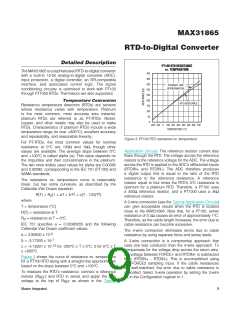
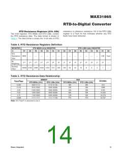
Linearizing Temperature Data
For a temperature range of -100NC to +100NC, a good
approximation of temperature can be made by simply
using the RTD data as shown below:
requested by the master. During a fault detection cycle
the MAX31865 has the ability to disconnect the FORCE-
input from its GND2 return path by means of and internal
analog switch.
Temperature (NC) ≈ (ADC code/32) – 256
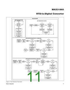
The conditions that generate a fault are listed below, see
Figure 4 for a fault detection flowchart.
This equation gives 0NC error at 0NC, -1.75NC error
at -100NC, and -1.4NC error at +100NC (assuming an
•ꢀ Detectedꢀatꢀanyꢀpointꢀinꢀtime
IEC751 RTD and R
equal to four times the 0 NC RTD
REF
Overvoltage (> V ) or undervoltage (< GND1) con-
DD
dition on FORCE+, FORCE2, RTDIN+, RTDIN-, or
FORCE- pins
resistance). For high precision, use the Callendar-Van
Dusen equation (in the Temperature Conversion section)
or a looꢀup table to correct the RTD’s predictable
nonlinearity.
•ꢀ DetectedꢀeveryꢀADCꢀconversion
Greater than or equal to threshold high conversion result
Less than or equal to threshold low conversion result
Using Thermistors
Other resistive sensors, such as thermistors (NTCs or
PTCs) may be used. Select an R
that is greater than
•ꢀ Detectedꢀ onꢀ demandꢀ byꢀ initiatingꢀ aꢀ Faultꢀ Detectionꢀ
REF
or equal to the sensor’s maximum resistance over the
temperature range of interest. The output data is the ratio
of the sensor resistance to the reference resistance.
Cycle (Configuration Register bits (D[3:2])
V
V
open
- > 0.85 x V
- < 0.85 x V
REFIN
BIAS
when FORCE- input switch is
when FORCE- input switch is
REFIN
BIAS
Analog-to-Digital Converter (ADC)
The ADC has fully differential analog inputs, RTDIN+
and RTDIN-, and fully differential reference inputs,
REFIN+ and REFIN-. The output code represents the
ratio between the analog input voltage and the reference
voltage. A negative input voltage produces an output
code of 0. An input voltage greater than the reference
voltage produces a full-scale output.
V
open
- < 0.85 x V
BIAS
RTDIN
FORCE+, FORCE2, FORCE-, RTDIN+, and RTDIN- are
protected against input voltages up to Q50V. Signals
applied to these pins are gated by analog switches that
open when the applied voltage is typically greater than
V
+ 100mV or less than GND1 - 400mV. Note that
DD
Input noise is attenuated by a third-order digital “sinc”
filter. Noise from 50Hz or 60Hz power sources (including
harmonics of the ac power’s fundamental frequency) is
attenuated by 82dB.
when a voltage fault occurs, the protection circuits may
allow approximately 350FA of current flow. This fault-
induced leaꢀage current does not cause any damage to
the MAX31865.
Fault Detection and Input Protection
The MAX31865 detects a variety of faults that can
occur with the external RTD and 2-, 3-, or 4-wire cables.
Some faults are detected on every conversion, while
others are detected only when a fault detection cycle is
When an overvoltage or undervoltage condition is
detected, bit D2 of the Fault Status register is set and the
ADC halts conversion updates until the fault is no longer
detected, at which point conversions resume.
Maxim Integrated
10

 MAXIM [ MAXIM INTEGRATED PRODUCTS ]