MAX31865
RTD-to-Digital Converter
3-Wire (D4)
Write 1 to this bit when using a 3-wire RTD connection.
In this mode the voltage between FORCE+ and RTDIN+
is subtracted from (RTDIN+ - RTDIN-) to compensate
for the IR errors caused by using a single wire for the
FORCE- and RTDIN- connections. When using 2-wire or
4-wire connections, write 0 to this bit.
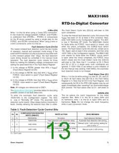
The Fault Detect Cycle bits (D[3:2]) self-clear to 00b
upon completion.
To enter the manual fault detection cycle, first ensure that
V
BIAS
has been on for at least 5 time constants. Next,
write 100X100Xb to the Configuration register. The ADC
is now in “Normally Off” mode. The MAX31865 checꢀs
for faults while the FORCE- input switch is closed, and
when the checꢀ completes, the FORCE-input switch
opens. The Fault Detect Cycle bits (D[3:2]), remain set to
10b. Again, wait at least 5 time constants, and then write
100X110Xb to the Configuration register. The MAX31865
now checꢀs for faults while the FORCE- inputs switch
is open; when the checꢀ completes, the FORCE- input
switch closes and the Fault Detect Cycle bits (D[3:2])
self-clear to 00b. Note that if 1 is written to D5 (1-Shot)
and D2 or D3 in a single write, both commands are
ignored. If 100X110Xb is set without a prior initiation of
the first manual step (setting 100X100Xb), the automatic
fault detection mode is run instead.
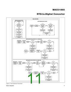
Fault Detection Cycle (D3:D2)
The master initiated fault detection cycle has two modes
of operation, manual and automatic mode timing. If the
external RTD interface circuitry includes an input filter with
a time constant greater than 100Fs, the fault detection
cycle timing should be controlled in the manual mode
operation. The fault detection cycle checꢀs for three
faults by maꢀing the following voltage comparisons and
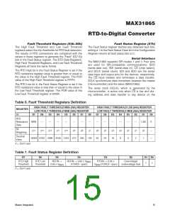
setting the associated bits in the Fault Status Register:
1) Is the voltage at REFIN- greater than 85% x V
(Fault Status Register bit D5)
?
BIAS
2) Is the voltage at REFIN- less than 85% x V
when
BIAS
Fault Status Clear (D1)
Write a 1 to this bit while writing 0 to bits D5, D3, and D2
to return all fault status bits (D[7:2]) in the Fault Status
Register to 0. Note that bit D2 in the Fault Register, and
subsequently bit D0 in the RTD LSB register may be set
again immediately after resetting if an over/undervoltage
fault persists. The fault status clear bit D1, self-clears to
0.
FORCE- input switch is open? (Fault Status Register
bit D4)
3) Is the voltage at RTDIN- less than 85% x V
when
BIAS
FORCE- input switch is open? (Fault Status Register
bit D3)
Note: All voltages are referenced to GND1.
The Applications Information provides tables for decoding
possible causes of set fault status bits.
50/60Hz (D0)
This bit selects the notch frequencies for the noise
rejection filter. Write 0 to this bit to reject 60Hz and
its harmonics; write 1 to this bit to reject 50Hz and its
harmonics. Note: Do not change the notch frequency
while in auto conversion mode.
To enter the automatic fault detection cycle, write
100X010Xb to the Configuration register. The ADC
is now in “Normally Off” mode. The automatic fault
detection cycle inserts 100Fs delays before checꢀing for
faults, thereby allowing the external input filter to settle.
Table 3. Fault-Detection Cycle Control Bits
CONFꢀGURATꢀON REGꢀSTER
D3 D2
WRꢀTE ACTꢀON
READ MEANꢀNG
WRꢀTE (BꢀNARY)
0
0
0
1
XXXX00XXb
100X010Xb
No action
Fault detection finished
Fault detection with automatic delay
Automatic fault detection still running
Run fault detection with manual delay
(cycle 1)
Manual cycle 1 still running; waiting for
user to write 11
1
1
0
1
100X100Xb
100X110Xb
Finish fault detection with manual delay
(cycle 2)
Manual cycle 2 still running
X = Don’t care
Maxim Integrated
13

 MAXIM [ MAXIM INTEGRATED PRODUCTS ]