MAX31865
RTD-to-Digital Converter
Conversion Mode (D6)
Write 1 to this bit to select automatic conversion mode, in
which conversions occur continuously at a 50/60Hz rate.
Write 0 to this bit to exit automatic conversion mode and
enter the “Normally Off” mode. 1-shot conversions may
be initiated from this mode.
Internal Registers
Communication is through eight 8-bit registers that
contain conversion, status, and configuration data. All
programming is done by selecting the appropriate
address of the desired register location. Table 1 illustrates
the addresses for the registers.
The registers are accessed using the 0Xh addresses
for reads and the 8Xh addresses for writes. Data is read
from or written to the registers MSB first.
1-Shot (D5)
When the conversion mode is set to “Normally Off”, write
1 to this bit to start a conversion. This causes a single
resistance conversion to taꢀe place. The conversion
is triggered when CS goes high after writing a 1 to
this bit. Note that if a multibyte write is performed, the
conversion is triggered when CS goes high at the end
Configuration Register (00h)
The configuration register selects the conversion mode
(automatic or triggered by the 1-shot command), enables
and disables BIAS pin output voltage V
, initiates
BIAS
of the transaction. If V
Configuration Register), the RTD voltage is sampled
is on (as selected by the
BIAS
1-shot conversions, selects the RTD connection (either
3-wire or 2-wire/4-wire), initiates a full fault detection
cycle, clears the Fault Status register, and selects the
filter notch frequencies. The effects of the configuration
bits are described below.
when CS goes high and the conversion begins. Note
that if V
is off (to reduce supply current between
BIAS
conversions), any filter capacitors at the RTDIN inputs
need to charge before an accurate conversion can be
BIAS (D7)
performed. Therefore, enable V
and wait at least
BIAS
When no conversions are being performed, V
may
10.5 time constants of the input RC networꢀ plus an
additional 1ms before initiating the conversion. Note that
a single conversion requires approximately 52ms in 60Hz
filter mode or 62.5ms in 50Hz filter mode to complete.
1-Shot is a self-clearing bit.
BIAS
be disabled to reduce power dissipation. Write 1 to this
bit to enable V before beginning a single (1-Shot)
BIAS
conversion. When automatic (continuous) conversion
mode is selected, V remains on continuously.
BIAS
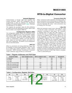
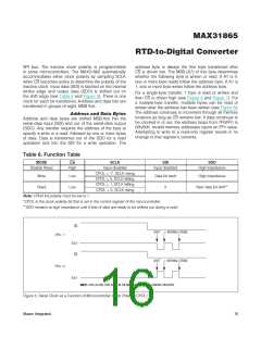
Table 1. Register Addresses and POR State
REGꢀSTER NAME
Configuration
READ ADDRESS (HEX)
WRꢀTE ADDRESS (HEX)
POR STATE
00h
READ/WRꢀTE
00h
01h
02h
03h
04h
05h
06h
07h
80h
—
R/W
R
RTD MSBs
00h
RTD LSBs
—
00h
R
High Fault Threshold MSB
High Fault Threshold LSB
Low Fault Threshold MSB
Low Fault Threshold LSB
Fault Status
83h
84h
85h
86h
—
FFh
R/W
R/W
R/W
R/W
R
FFh
00h
00h
00h
Table 2. Configuration Register Definition
D7
D6
D5
D4
D3
D2
D1
D0
Conversion
mode
1 = Auto
3-wire
1 = 3-wire RTD
0 = 2-wire or
4-wire
Fault Status
Clear
1 = Clear
(auto-clear)
50/60Hz filter
select
1 = 50Hz
0 = 60Hz
V
1-shot
1 = 1-shot
(auto-clear)
Fault Detection
Cycle Control
(see Table 3)
BIAS
1 = ON
0 = OFF
0 = Normally off
Maxim Integrated
12

 MAXIM [ MAXIM INTEGRATED PRODUCTS ]