MAX31865
RTD-to-Digital Converter
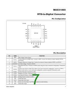
Pin Description (continued)
PꢀN
15
NAME
DGND
GND1
N.C.
FUNCTꢀON
Digital Ground
16
Analog Ground. Connect to GND2.
Do Not Connect
17
Active-Low Push-Pull Data-Ready Output. DRDY goes low when a new conversion result is available in
the data register. When a read-operation of an RTD resistance data register occurs, DRDY returns high.
18
19
DRDY
Digital Supply Voltage Input. Connect to a 3.3V power supply. Bypass to DGND with a 0.1FF bypass
capacitor.
DVDD
Analog Supply Voltage Input. Connect to a 3.3V power supply. Bypass to GND1 with a 0.1FF bypass
capacitor.
20
—
V
DD
EP
Exposed Pad (Bottom Side of Pacꢀage). Connect to GND1.
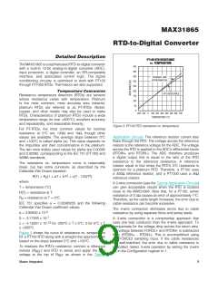
Block Diagram
V
DD
DVDD
V
V
DD
DVDD
BIAS
VBIAS
GENERATOR
REFIN+
REFIN-
SCLK
SDO
SDI
SERIAL
LOGIC
DATA REGISTERS
ISENSOR
FORCE+
FORCE2
RTDIN+
CS
DIGITAL LOGIC
3-WIRE
ONLY
DIGITAL
COMPARATOR
FOR
50/60Hz DIGITAL
SINC FILTER
15-BIT
Σ∆ ADC
FAULT DETECTION
±±50 ꢀPOTꢁCTIOꢂ
MASTER-INITIATED
FAULT-DETECTION
CYCLE
DRDY
ADC STATE
MACHINE
RTDIN-
FORCE-
MAX31865
GND2 GND1
DGND
Maxim Integrated
8

 MAXIM [ MAXIM INTEGRATED PRODUCTS ]