MAX17047/MAX17050
ModelGauge m3 Fuel Gauge
enable the thermistor bias switch. With a standard 10kI
thermistor, this adds an additional ~200FA to the current
Status and Configuration
drain of the circuit. This bit is set to 0 at power-up.
The following registers control operation of the ALRT inter-
rupt feature, control transition between active and shut-
down modes of operation, and provide status updates to
the host processor.
ETHRM—Enable Thermistor. Set to logic 1 to enable
the automatic THRM output bias and AIN measurement
every 1.4s. This bit is set to 1 at power-up.
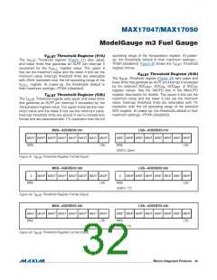
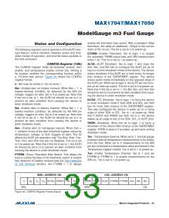
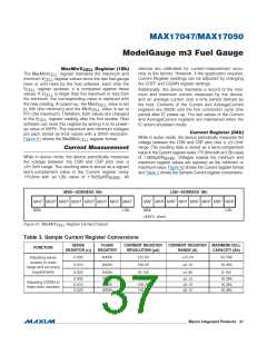
CONFIG Register (1Dh)
The CONFIG register holds all shutdown enable, alert
enable, and temperature enable control bits. Writing a
bit location enables the corresponding function within
a 175.8ms task period. Figure 44 shows the CONFIG
register format.
ALSH—ALRT Shutdown. Set to logic 1 and clear the
Aen, Ber, and Bei bits to configure the ALRT pin as an
input to control shutdown mode of the device. The device
enters shutdown if the ALRT pin is held active for longer
than timeout of the SHDNTIMER register. The device
enters active mode immediately on the opposite edge of
the ALRT pin. When set to logic 0, the ALRT pin can func-
tion as an interrupt output. This bit is set to 0 at power-up.
Note that if this bit is set to 1, the Bei, Ber, and Aen bits
should be set to 0 to prevent an alert condition from caus-
ing the device to enter shutdown mode.
0—Bit must be written 0. Do not write 1.
Ber—Enable alert on battery removal. When Ber = 1, a
battery-removal condition, as detected by the AIN pin
voltage, triggers an alert. Set to 0 at power-up. Note that
if this bit is set to 1, the ALSH bit should be set to 0 to
prevent an alert condition from causing the device to
enter shutdown mode.
2
I2CSH—I C Shutdown. Set to logic 1 to force the device
to enter shutdown mode if both SDA and SCL are held
low for more than timeout of the SHDNTIMER register.
This also configures the device to wake up on a rising
edge of either SDA or SCL. Set to 1 at power-up. Note
that if I2SCH and AINSH are both set to 0, the device
wakes up an edge of any of the SDA, SCL, or ALRT pins.
Bei—Enable alert on battery insertion. When Bei = 1, a
battery-insertion condition, as detected by the AIN pin
voltage, triggers an alert. Set to 0 at power-up. Note that
if this bit is set to 1, the ALSH bit should be set to 0 to
prevent an alert condition from causing the device to
enter shutdown mode.
SHDN—Shutdown. Write this bit to logic 1 to force a
shutdown of the device after timeout of the SHDNTIMER
register. SHDN is reset to 0 at power-up and upon exiting
shutdown mode.
Aen—Enable alert on fuel-gauge outputs. When Aen =
1, violation of any of the alert threshold register values by
temperature, voltage, or SOC triggers an alert. This bit
affects the ALRT pin operation only. The Smx, Smn, Tmx,
Tmn, Vmx, and Vmn bits are not disabled. This bit is set
to 0 at power-up. Note that if this bit is set to 1, the ALSH
bit should be set to 0 to prevent an alert condition from
causing the device to enter shutdown mode.
Tex—Temperature External. When set to 1, the fuel gauge
requires external temperature measurements to be written
from the host. When set to 0, measurements on the AIN
pin are converted to a temperature value and stored in the
Temperature register instead. Tex is set to 1 at power-up.
Ten—Enable Temperature Channel. Set to 1 and set
ETHRM or FTHRM to 1 to enable measurements on the
AIN pin. Ten is set to 1 at power-up.
FTHRM—Force Thermistor Bias Switch. This allows the
host to control the bias of the thermistor switch or enable
fast detection of battery removal (see the Fast Detection
of Cell Removal section). Set FTHRM = 1 to always
MSB—ADDRESS 1Dh
LSB—ADDRESS 1Dh
0
S
T
V
S
ALRTp AINSH Ten Tex
LSb
SHDN I2CSH ALSH ETHRM FTHRM Aen Bei Ber
S
S
MSb
MSb
LSb
Figure 44. CONFIG Register Format (Input)
���������������������������������������������������������������� Maxim Integrated Products 33

 MAXIM [ MAXIM INTEGRATED PRODUCTS ]