MAX17047/MAX17050
ModelGauge m3 Fuel Gauge
AINSH—AIN Pin Shutdown. Set to 1 to enable device shut-
down when the battery is removed. The IC enters shutdown
if the AIN pin remains high (AIN reading > V - V
for longer than the timeout of the SHDNTIMER register. This
also configures the device to wake up when AIN is pulled low
on cell insertion. AINSH is set to 0 at power-up. Note that if
I2SCH and AINSH are both set to 0, the device wakes up an
edge of any of the SDA, SCL, or ALRT pins.
alerts are cleared automatically when the threshold is no
longer exceeded. S is set to 0 at power-up.
S
)
DETR
THRM
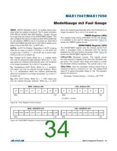
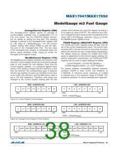
TIMER Register (3Eh)
This register holds timing information for the fuel gauge.
It is available to the user for debug purposes. Figure 45
shows the TIMER register format.
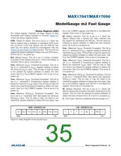
SHDNTIMER Register (3Fh)
The SHDNTIMER register sets the timeout period from
when a shutdown event is detected until the device
disables the LDO and enters low-power mode. Figure 46
shows the SHDNTIMER register format.
ALRTp—ALRT Pin Polarity. Regardless if ALRT is being
used as an input or output, if ALRTp = 0, the ALRT pin
is active low; if ALRTp = 1, the ALRT pin is active high.
ALRTp is set to 0 at power-up.
CTR12:CTR0—Shutdown Counter. This register counts
the total amount of elapsed time since the shutdown trig-
ger event. This counter value stops and resets to 0 when
the shutdown timeout completes. The counter LSb is 1.4s.
V —Voltage ALRT Sticky. When V = 1, voltage alerts
S
S
can only be cleared through software. When V = 0, volt-
S
age alerts are cleared automatically when the threshold
is no longer exceeded. V is set to 0 at power-up.
S
THR2:THR0—Sets the shutdown timeout period from a
minimum of 45s to a maximum of 1.6h. The default POR
value of 7h gives a shutdown delay of 1.6h. The equation
setting the period is:
T —Temperature ALRT Sticky. When T = 1, tempera-
S
S
ture alerts can only be cleared through software. When
= 0, temperature alerts are cleared automatically
T
S
when the threshold is no longer exceeded. T is set to 1
S
(8+THR)
at power-up.
Shutdown Timeout Period = 175.8ms O 2
S —SOC ALRT Sticky. When S = 1, SOC alerts can
S
S
only be cleared through software. When S = 0, SOC
S
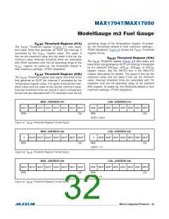
MSB—Address 3Eh
LSB—Address 3Eh
215
214
213
212
211
210
29
28
27
26
25
24
23
22
21
20
MSb
LSb
MSb
LSb
20 UNITS: 175.8ms
Figure 45. Timer Register Format (Output)
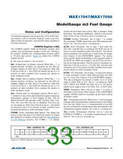
MSB—ADDRESS 3Fh
LSB—ADDRESS 3Fh
2
1
0
12
11
10
9
8
7
6
5
4
3
2
1
0
THR THR THR CTR
CTR
CTR
CTR CTR
CTR CTR CTR CTR CTR CTR CTR CTR
MSb
LSb
MSb LSb
Figure 46. SHDNTIMER Register Format (Input/Output)
���������������������������������������������������������������� Maxim Integrated Products 34

 MAXIM [ MAXIM INTEGRATED PRODUCTS ]