MAX17047/MAX17050
ModelGauge m3 Fuel Gauge
These shutdown entry modes are all programmable
nal. Note that if the pin is configured to be logic-low when
inactive, the external pullup increases current drain.
according to application. Shutdown events are gated
by the SHDNTIMER register, which allows a long delay
between the shutdown event and the actual shutdown.
By behaving this way, the device takes the best reading
of the relaxation voltage.
The ALRTp bit in the CONFIG register sets the polarity of
the ALRT pin output. Alerts can be triggered by any of the
following conditions:
•ꢀ Battery removal—(V
> V
- V
) and bat-
tery removal detection enabled (Ber = 1).
•ꢀ Battery insertion—(V ꢀ<ꢀV - V ) and bat-
DETF
AIN
THRM
DETR
Exiting shutdown:
2
•ꢀ I C Wakeup—Any edge on SCL/SDA.
AIN
THRM
•ꢀ ALRT Wakeup—Any edge on ALRT line and (ALSH =
tery insertion detection enabled (Bei = 1).
•ꢀ Over-/undervoltage—V threshold violation
(upper or lower) and alerts enabled (Aen = 1).
•ꢀ Over-/undertemperature—T threshold violation
1 or I2CSH = ALSH = 0).
ALRT
•ꢀ Reset—IC is power cycled.
See the Status and Configuration section for detailed
descriptions of the SHDNTIMER and CONFIG registers.
ALRT
(upper or lower) and alerts enabled (Aen = 1).
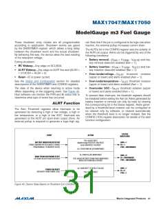
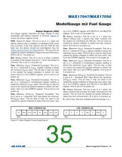
The state of the device when returning to active mode
differs depending on the triggering event. See Figure 40.
Host software can monitor the POR and Bi status bits to
determine what type of event has occurred.
•ꢀ Over/under SOC—S threshold violation (upper
ALRT
or lower) and alerts enabled (Aen = 1).
To prevent false interrupts, the threshold registers should
be initialized before setting the Aen bit. Alerts generated by
battery insertion or removal can only be reset by clearing
the corresponding bit in the Status register. Alerts gener-
ated by a threshold-level violation can be configured to
be cleared only by software, or cleared automatically
when the threshold level is no longer violated. See the
CONFIG (1Dh) register description for details of the alert
function configuration.
ALRT Function
The Alert Threshold registers allow interrupts to be
generated by detecting a high or low voltage, a high or
low temperature, or a high or low SOC. Interrupts are
generated on the ALRT pin open-drain output driver. An
external pullup is required to generate a logic-high sig-
STATUS
INDICATORS
EVENT
ACTION
FUEL GAUGE RESET
MaxMinVoltage REGISTER (1Bh) RESET
Cycles REGISTER (17h) RESET
BATTERY INSERTION DETECTED
(THRM COMPARATOR RECOGNIZES CHANGE
FROM REMOVAL TO INSERTED STATE)
DNR = 1
Bi = 1
POR = UNCHANGED
ALL OTHER RAM VALUES MAINTAINED
ALL RAM VALUES MAINTAINED
DNR = 0
Bi = UNCHANGED
POR = UNCHANGED
WAKE FROM SHUTDOWN STATE
(I C EDGE OR ALRT EDGE DETECTED)
2
FUEL GAUGE RESTARTS FROM POINT MAINTAINED
WHEN SHUTDOWN WAS ENTERED
ALL RAM RESET TO DEFAULT VALUES
FUEL GAUGE RESET
DNR = 1
Bi = 0
POR = 1
POWER-ON RESET
(RECOVERY FROM POWER LOSS)
Figure 40. Device State Based on Shutdown Exit Condition
���������������������������������������������������������������� Maxim Integrated Products 31

 MAXIM [ MAXIM INTEGRATED PRODUCTS ]