MAX17047/MAX17050
ModelGauge m3 Fuel Gauge
Detection occurs by monitoring the AIN pin voltage com-
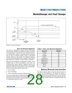
newly inserted cell. This process can take up to 1.845s
(FTHRM = 0) or 620ms (FTHRM = 1) from time of inser-
tion. Note that the device uses the cell voltage as a start-
ing point for the fuel gauge. If the cell voltage is not fully
relaxed at time of insertion, the fuel gauge begins with
some initial error. See the Fuel-Gauge Learning section
for details. The host can disable this feature by clearing
the enBi1 bit in the MiscCFG register.
pared to the THRM pin. Whenever a cell is present, the
external resistor-divider network sets the voltage of AIN.
When the cell is removed, the remaining external resistor
pulls AIN to the THRM pin voltage level. Whenever V
AIN
<ꢀ V
- V
, the device determines that a cell is
THRM
DETF
present in the application. If V
> V
- V
, the
DETR
AIN
THRM
device determines that no cell is present at that time.
The device can also be configured to alert the host when
cell insertion occurs. When Bei = 1 in the CONFIG reg-
ister, the device generates an interrupt on the ALRT pin
at the start of the first temperature conversion after inser-
tion. This could take up to 1.4s to occur. This feature is
useful if the application uses more than one cell type and
the IC must be reconfigured at each insertion.
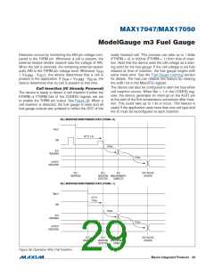
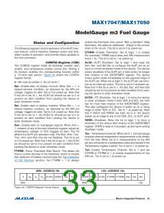
Cell Insertion (IC Already Powered)
The device is ready to detect a cell insertion if either the
ETHRM or FTHRM bits of the CONFIG register are set
to enable the THRM pin output. See Figure 38. When a
cell insertion is detected, the fuel gauge is reset and all
fuel-gauge outputs are updated to reflect the SOC of the
CELL INSERTION FROM POWERED STATE (FTHRM = 0)
V
BATT
AIN
UP TO 1.4s
270ms
A/D
READINGS
175ms
OUTPUT
REGISTERS
CELL
INSERTION
CELL
INSERTION MEASUREMENTS
DETECTED COMPLETE
A/D
SOC VALUES
UPDATED
CELL INSERTION FROM POWERED STATE (FTHRM = 1)
V
BATT
AIN
UP TO
175ms
270ms
A/D
READINGS
175ms
OUTPUT
REGISTERS
CELL
INSERTION
CELL
INSERTION MEASUREMENTS
DETECTED COMPLETE
A/D
SOC VALUES
UPDATED
Figure 38. Operation After Cell Insertion
���������������������������������������������������������������� Maxim Integrated Products 29

 MAXIM [ MAXIM INTEGRATED PRODUCTS ]