8- and 4-Channel, 3 ꢀ ꢁREF
Multirange Inputs, Serial 14-Bit ADCs
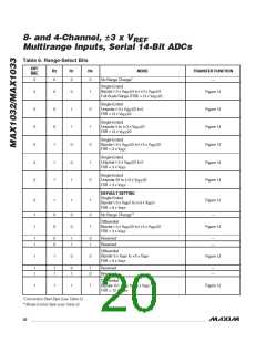
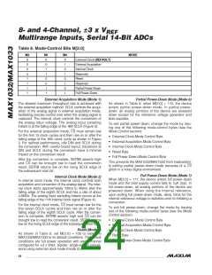
Table 8. Mode-Control Bits M[2:0]
M2
0
M1
0
M0
0
MODE
External Clock (DEFAULT)
External Acquisition
Internal Clock
0
0
1
0
1
0
0
1
1
Reserved
1
0
0
Reset
1
0
1
Reserved
1
1
0
Partial Power-Down
Full Power-Down
1
1
1
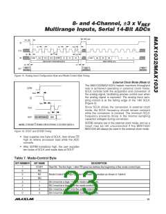
External Acquisition Mode (Mode 1)
Partial Power-Down Mode (Mode 6)
The slowest maximum throughput rate is achieved with
the external acquisition method. SCLK controls the acqui-
sition of the analog signal in external acquisition mode,
facilitating precise control over when the analog signal is
captured. The internal clock controls the conversion of
the analog input voltage. The analog input sampling
instant is at the falling edge of the 16th SCLK (Figure 3).
As shown in Table 8, when M[2:0] = 110, the device
enters partial power-down mode. In partial power-
down, all analog portions of the device are powered
down except for the reference voltage generator and
bias supplies.
2/MAX103
To exit partial power-down, change the mode by issu-
ing one of the following mode-control bytes (see the
Mode Control section):
For the external acquisition mode, CS must remain low
for the first 15 clock cycles and then rise on or after the
falling edge of the 16th clock cycle as shown in Figure
3. For optimal performance, idle DIN and SCLK during
the conversion. With careful board layout, transitions at
DIN and SCLK during the conversion have a minimal
impact on the conversion result.
• External-Clock-Mode Control Byte
• External-Acquisition-Mode Control Byte
• Internal-Clock-Mode Control Byte
• Reset Byte
• Full Power-Down-Mode Control Byte
After the conversion is complete, SSTRB asserts high
and CS can be brought low to read the conversion
result. SSTRB returns low on the rising SCLK edge of
the subsequent start bit.
This prevents the MAX1032/MAX1033 from inadvertent-
ly exiting partial power-down mode because of a CS
glitch in a noisy digital environment.
Full Power-Down Mode (Mode 7)
When M[2:0] = 111, the device enters full power-down
mode and the total supply current falls to 1µA (typ). In
full power-down, all analog portions of the device are
powered down. When using the internal reference,
upon exiting full power-down mode, allow 10ms for the
internal reference voltage to stabilize prior to initiating a
conversion.
Internal Clock Mode (Mode 2)
In internal clock mode, the internal clock controls both
acquisition and conversion of the analog signal. The inter-
nal clock starts approximately 100ns to 400ns after the
falling edge of the eighth SCLK and has a rate of about
4.5MHz. The analog input sampling instant occurs at the
falling edge of the 11th internal clock signal (Figure 4).
For the internal clock mode, CS must remain low for the
first seven SCLK cycles and then rise on or after the
falling edge of the eighth SCLK cycle. After the conver-
sion is complete, SSTRB asserts high and CS can be
brought low to read the conversion result. SSTRB returns
low on the rising SCLK edge of the subsequent start bit.
To exit full power-down, change the mode by issuing
one of the following mode-control bytes (see the Mode
Control section):
• External-Clock-Mode Control Byte
• External-Acquisition-Mode Control Byte
• Internal-Clock-Mode Control Byte
• Reset Byte
Reset (Mode 4)
As shown in Table 8, set M[2:0] = 100 to reset the
MAX1032/MAX1033 to its default conditions. The default
conditions are full power operation with each channel
• Partial Power-Down-Mode Control Byte
configured for 3 x V
, bipolar, single-ended conver-
REF
sions using external clock mode (mode 0).
24 ______________________________________________________________________________________

 MAXIM [ MAXIM INTEGRATED PRODUCTS ]