8- and 4-Channel, 3 ꢀ ꢁREF
Multirange Inputs, Serial 14-Bit ADCs
Full-Power Bandwidth
Unipolar Offset Error
A 95% of full-scale sine wave is applied to the ADC,
and the input frequency is then swept up to the point
where the amplitude of the digitized conversion result
has decreased by -3dB.
-FSR to 0V
When a zero-scale analog input voltage is applied to
the converter inputs, the digital output is all ones
(0x3FFF). Ideally, the transition from 0x3FFF to 0x3FFE
occurs at AGND1 - 0.5 LSB. Unipolar offset error is the
amount of deviation between the measured zero-scale
transition point and the ideal zero-scale transition point,
with all untested channels grounded.
Common-Mode Rejection Ratio (CMRR)
CMRR is the ability of a device to reject a signal that is
“common” to or applied to both input terminals. The
common-mode signal can be either an AC or a DC sig-
nal or a combination of the two. CMR is expressed in
decibels. Common-mode rejection ratio is the ratio of
the differential signal gain to the common-mode signal
gain. CMRR applies only to differential operation.
0V to +FSR
When a zero-scale analog input voltage is applied to
the converter inputs, the digital output is all zeros
(0x0000). Ideally, the transition from 0x0000 to 0x0001
occurs at AGND1 + 0.5 LSB. Unipolar offset error is the
amount of deviation between the measured zero-scale
transition point and the ideal zero-scale transition point,
with all untested channels grounded.
Power-Supply Rejection Ratio (PSRR)
PSRR is the ratio of the output-voltage shift to the
power-supply-voltage shift for a fixed input voltage. For
the MAX1032/MAX1033, AVDD1 can vary from 4.75V to
5.25V. PSRR is expressed in decibels and is calculated
using the following equation:
2/MAX103
Bipolar Offset Error
When a zero-scale analog input voltage is applied to
the converter inputs, the digital output is a one followed
by all zeros (0x2000). Ideally, the transition from
0x1FFF to 0x2000 occurs at (2N-1 - 0.5)LSB. Bipolar off-
set error is the amount of deviation between the mea-
sured midscale transition point and the ideal midscale
transition point, with untested channels grounded.
⎛
⎞
⎟
5.25V − 4.75V
− V
PSRR[dB] = 20 × log
⎜
V
⎝
OUT(5.25V)
OUT(4.75V) ⎠
For the MAX1032/MAX1033, PSRR is tested in bipolar
operation with the analog inputs grounded.
Gain Error
When a positive full-scale voltage is applied to the con-
verter inputs, the digital output is all ones (0x3FFF). The
transition from 0x3FFE to 0x3FFF occurs at 1.5 LSB
below full scale. Gain error is the amount of deviation
between the measured full-scale transition point and
the ideal full-scale transition point with the offset error
removed and all untested channels grounded.
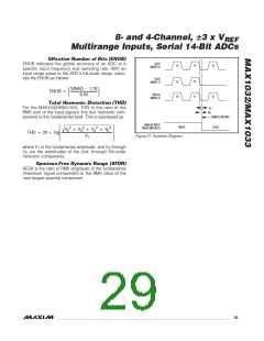
Aperture Jitter
Aperture jitter, t , is the statistical distribution of the
AJ
variation in the sampling instant (Figure 21).
Aperture Delay
Aperture delay, t , is the time from the falling edge of
AD
SCLK to the sampling instant (Figure 21).
Signal-to-Noise Ratio (SNR)
SNR is computed by taking the ratio of the RMS signal
to the RMS noise. RMS noise includes all spectral com-
ponents to the Nyquist frequency excluding the funda-
mental, the first five harmonics, and the DC offset.
Unipolar Endpoint Overlap
Unipolar endpoint overlap is the change in offset when
switching between complementary input voltage
ranges. For example, the difference between the volt-
age that results in a 0x3FFF output in the -3 x V
/2 to
REF
0V input voltage range and the voltage that results in a
Signal-to-Noise Plus Distortion (SINAD)
SINAD is computed by taking the ratio of the RMS sig-
nal to the RMS noise plus distortion. RMS noise plus
distortion includes all spectral components to the
Nyquist frequency excluding the fundamental and the
DC offset.
0x0000 output in the 0 to +3 x V /2 input voltage
REF
range is the unipolar endpoint overlap. The unipolar
endpoint overlap is positive for the MAX1032/MAX1033,
preventing loss of signal or a dead zone when switch-
ing between adjacent analog input voltage ranges.
Small-Signal Bandwidth
⎛
⎞
Signal
Noise
A 100mV
sine wave is applied to the ADC, and the
RMS
P-P
SINAD(dB) = 20 × log
⎜
⎟
input frequency is then swept up to the point where the
amplitude of the digitized conversion result has
decreased by -3dB.
⎝
⎠
RMS
28 ______________________________________________________________________________________

 MAXIM [ MAXIM INTEGRATED PRODUCTS ]