DS2413: 1-Wire Dual Channel Addressable Switch
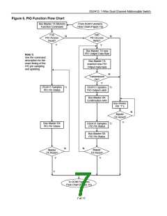
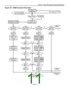
Figure 6. PIO Function Flow Chart
From ROM Functions
Bus Master TX Memory
Flow Chart (Figure 10)
Function Command
F5h
5Ah
N
N
PIO Access
PIO Access
Write?
Read?
Y
Y
Bus Master TX new
PIO Output Data Byte
Note 1)
See the command
description for the
exact timing of the
PIO pin sampling
and updating.
Bus Master TX
inverted new PIO
Output Data Byte
N
Transmission
OK?
Y
DS2413 Samples
PIO Pin Status
DS2413 Updates
PIO Output Latch
Bus Master RX
Confirmation AAh
Bus Master
RX “1”s
N
Master
TX Reset?
Y
Bus Master RX
PIO Pin Status
DS2413 Samples
PIO Pin Status
Bus Master RX
PIO Pin Status
N
N
Master
Master
TX Reset?
TX Reset?
Y
Y
Y
To ROM Functions
Flow Chart (Figure 10)
7 of 17

 MAXIM [ MAXIM INTEGRATED PRODUCTS ]