DS2413: 1-Wire Dual Channel Addressable Switch
The idle state for the 1-Wire bus is high. If for any reason a transaction needs to be suspended, the bus MUST be
left in the idle state if the transaction is to resume. If this does not occur and the bus is left low for more than 16µs
(Overdrive speed) or more than 120µs (standard speed), one or more devices on the bus may be reset.
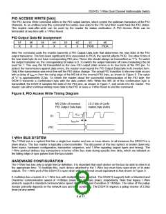
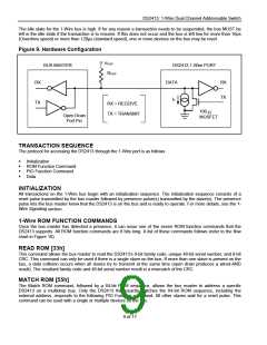
Figure 9. Hardware Configuration
VPUP
BUS MASTER
DS2413 1-Wire PORT
RPUP
RX
TX
DATA
RX
TX
IL
RX = RECEIVE
TX = TRANSMIT
100
ꢀ
Open Drain
Port Pin
MOSFET
TRANSACTION SEQUENCE
The protocol for accessing the DS2413 through the 1-Wire port is as follows:
Cꢀ Initialization
Cꢀ ROM Function Command
Cꢀ PIO Function Command
Cꢀ Data
INITIALIZATION
All transactions on the 1-Wire bus begin with an initialization sequence. The initialization sequence consists of a
reset pulse transmitted by the bus master followed by presence pulse(s) transmitted by the slave(s). The presence
pulse lets the bus master know that the DS2413 is on the bus and is ready to operate. For more details, see the 1-
Wire Signaling section.
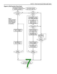
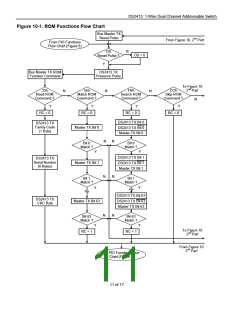
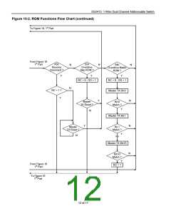
1-Wire ROM FUNCTION COMMANDS
Once the bus master has detected a presence, it can issue one of the seven ROM function commands that the
DS2413 supports. All ROM function commands are 8 bits long. A list of these commands follows (refer to the flow
chart in Figure 10).
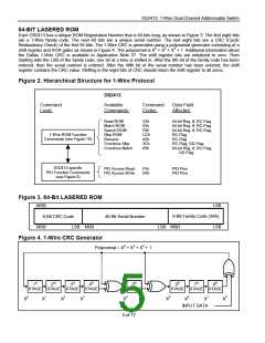
READ ROM [33h]
This command allows the bus master to read the DS2413’s 8-bit family code, unique 48-bit serial number, and 8-bit
CRC. This command can only be used if there is a single slave on the bus. If more than one slave is present on the
bus, a data collision occurs when all slaves try to transmit at the same time (open drain produces a wired-AND
result). The resultant family code and 48-bit serial number result in a mismatch of the CRC.
MATCH ROM [55h]
The Match ROM command, followed by a 64-bit ROM sequence, allows the bus master to address a specific
DS2413 on a multidrop bus. Only the DS2413 that exactly matches the 64-bit ROM sequence, including the
external address, responds to the following PIO Function command. All other slaves wait for a reset pulse. This
command can be used with a single or multiple devices on the bus.
9 of 17

 MAXIM [ MAXIM INTEGRATED PRODUCTS ]