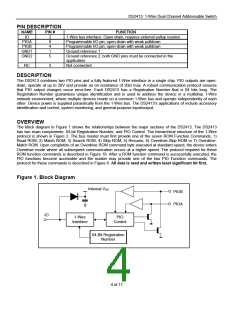
DS2413: 1-Wire Dual Channel Addressable Switch
PIO ACCESS WRITE [5Ah]
The PIO Access Write command writes to the PIO output latches, which control the pulldown transistors of the PIO
channels. In an endless loop this command first writes new data to the PIO and then reads back the PIO status.
This implicit read-after-write can be used by the master for status verification. A PIO Access Write can be
terminated at any time with a 1-Wire Reset.
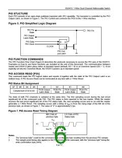
PIO Output Data Bit Assignment
b7
X
b6
X
b5
X
b4
X
b3
X
b2
X
b1
PIOB
b0
PIOA
After the command code the master transmits a PIO Output Data byte that determines the new state of the PIO
output transistors. The first (least significant) bit is associated to PIOA; the next bit affects PIOB. The other 6 bits of
the new state byte do not have corresponding PIO pins. These bits should always be transmitted as "1"s. To switch
the output transistor on, the corresponding bit value is 0. To switch the output transistor off (non-conducting) the bit
must be 1. This way the bit transmitted as the new PIO output state arrives in its true form at the PIO pin. To
protect the transmission against data errors, the master must repeat the PIO Output Data byte in its inverted form.
Only if the transmission was error-free will the PIO status change. The actual PIO transition to the new state occurs
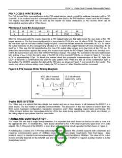
with a delay of tREH+x from the rising edge of the MS bit of the inverted PIO byte, as shown in Figure 8. The value
of "x" is approximately 0.2µs. To inform the master about the successful communication of the PIO byte, the
DS2413 transmits a confirmation byte with the data pattern AAh. While the MS bit of the confirmation byte is
transmitted, the DS2413 samples the state of the PIO pins, as shown in Figure 7, and sends it to the master. The
master can either continue writing more data to the PIO or issue a 1-Wire Reset to end the command.
Figure 8. PIO Access Write Timing Diagram
MS 2 bits of inverted
PIO Output Data byte
LS 2 bits of confir-
mation byte (AAh)
VTH
IO
tREH+x
PIO
1-Wire BUS SYSTEM
The 1-Wire bus is a system that has a single bus master and one or more slaves. In all instances the DS2413 is a
slave device. The bus master is typically a microcontroller. The discussion of this bus system is broken down into
three topics: hardware configuration, transaction sequence, and 1-Wire signaling (signal types and timing). The
1-Wire protocol defines bus transactions in terms of the bus state during specific time slots, which are initiated on
the falling edge of sync pulses from the bus master.
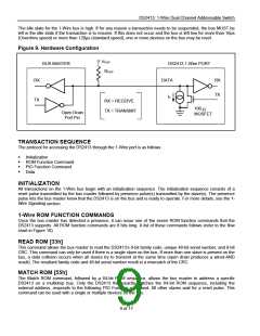
HARDWARE CONFIGURATION
The 1-Wire bus has only a single line by definition; it is important that each device on the bus be able to drive it at
the appropriate time. To facilitate this, each device attached to the 1-Wire bus must have open-drain or tri-state
outputs. The 1-Wire port of the DS2413 is open drain with an internal circuit equivalent to that shown in Figure 9.
A multidrop bus consists of a 1-Wire bus with multiple slaves attached. The DS2413 supports both a Standard and
Overdrive communication speed of 14.9kbps (max) and 100kbps (max), respectively. Note that legacy 1-Wire
products support a standard communication speed of 16.3kbps and Overdrive of 142kbps. The value of the pullup
resistor primarily depends on the network size and load conditions. The DS2413 requires a pullup resistor of 2.2kꢀ
(max) at any speed.
8 of 17

 MAXIM [ MAXIM INTEGRATED PRODUCTS ]