DS2413: 1-Wire Dual Channel Addressable Switch
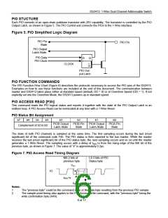
64-BIT LASERED ROM
Each DS2413 has a unique ROM Registration Number that is 64 bits long, as shown in Figure 3. The first eight bits
are a 1-Wire family code. The next 48 bits are a unique serial number. The last eight bits are a CRC (Cyclic
Redundancy Check) of the first 56 bits. The 1-Wire CRC is generated using a polynomial generator consisting of a
shift register and XOR gates as shown in Figure 4. The polynomial is X8 + X5 + X4 + 1. Additional information about
the Dallas 1-Wire CRC is available in Application Note 27. The shift register bits are initialized to zero. Then
starting with the LSB of the family code, one bit at a time is shifted in. After the 8th bit of the family code has been
entered, then the serial number is entered. After the 48th bit of the serial number has been entered, the shift
register contains the CRC value. Shifting in the eight bits of CRC should return the shift register to all zeros.
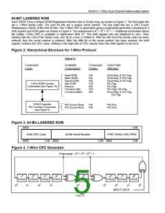
Figure 2. Hierarchical Structure for 1-Wire Protocol
DS2413
Command
Level:
Available
Command
Codes:
Data Field
Affected:
Commands:
Read ROM
Match ROM
Search ROM
Skip ROM
33h
55h
F0h
CCh
A5h
3Ch
69h
64-bit Reg. #, RC-Flag
64-bit Reg. #, RC-Flag
64-bit Reg. #, RC-Flag
RC-Flag
1-Wire ROM Function
Commands (see Figure 10)
Resume
RC-Flag
Overdrive Skip
Overdrive Match
RC-Flag, OD-Flag
64-bit Reg. #, RC-Flag,
OD-Flag
DS2413-specific
PIO Function Commands
(see Figure 6)
PIO Access Read
PIO Access Write
F5h
5Ah
PIO Pins
PIO Pins
Figure 3. 64-Bit LASERED ROM
MSB
LSB
8-Bit Family Code (3Ah)
LSB MSB LSB
8-Bit CRC Code
48-Bit Serial Number
MSB
LSB MSB
Figure 4. 1-Wire CRC Generator
Polynomial = X8 + X5 + X4 + 1
1st
2nd
3rd
4th
5th
STAGE
6th
7th
8th
STAGE STAGE
X1
STAGE STAGE
X3
STAGE STAGE STAGE
X0
X2
X4
X5
X6 X7
INPUT DATA
X8
5 of 17

 MAXIM [ MAXIM INTEGRATED PRODUCTS ]