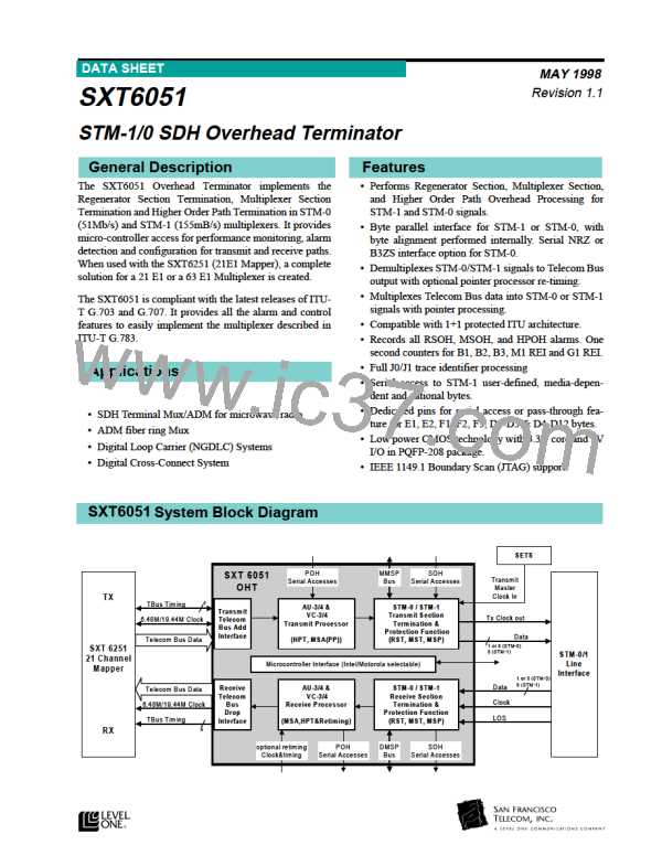
Functional Description
Figure 7:SXT6051 Receiver Blocks
SERIAL
RSOH
&MSOH
RSOH
Interface
MSOH Interface
MSP INTERFACE
DHICLK
DHPOSD
Serial Interface
DHNEGD
LOS
MSP block
Multiplexer section
receiver
Regenerator
Section
receiver
Framer
DHBDATA[7..0]
DHBCLK
Parallel
Interface
Pointer
processing
MHICLK
Clock
AISRX
RPOW1
RPOW2
RPOWC
RPOWBYC
B3OUT
distribution and
references
MHBCLKI
Higher order
path Receiver
ROPHFR
RPOHEN
RPOHCK
RPOH
DTBH4EN
DTBPAYEN
DTBTUGEN
DTBJ0J1EN
DTBCK
1
TO 3
Retiming
Function
DTBPAR
DHBDATA[7..0]
DRETCLK
DRETFRMI
Receive side SXT 6051
_ . - - 2/12/98
REC DETAILS VSD PAGE-1
Figure 8:STM-0 Robust Frame State Machine
Clock Distribution and Reference
Two separate inputs are supplied for Blue clock refer-
ences.
Locked In
Frame
• MHICLK is used for a serial reference clock in
the case of an STM-0 system. The frequency of a
serial reference clock is 51.84 MHz ±20ppm
check
fram es with Valid NDF
3 m ore consecutive
8
consecutive fram es
with Invalid NDF
4
consecutive fram es
with Errored FAS
• MHBCLKI is used for a parallel reference clock
in the case of either an STM-0 or an STM-1 sys-
tem. The frequency of the parallel reference
clock for STM 0 is 6.48 MHz ±20ppm and for
STM-1 19.44MHz ±20ppm
In Frame
Received
Fram e with
Invalid NDF
2
consecutive fram es
with Correct FAS and Valid NDF
Out Of
Frame
An active LOS can have two consequent actions that
can be enabled or disabled (see register 40H):
ROBUST ALG ORITHM FOR STM -0 FRAM ING
• Clock switches from receive clock to reference
clock
• Insert AIS towards the PDH network from the
RST section
Desynchronisation:Transition from Locked In Frame to Out Of Frame
Acquisition
Transition
:Transition from Out Of frame to In Frame State.
:Transition from In Frame State to Locked In Frame.
Framer
OOF Alarm is disabled and receive demultiplexer is re-synchronized, according to the new
frame boundary, when entering in the In Frame State.
The framer operates on either a parallel byte or a serial
bit stream. Two settings are available for the frame
acquisition state machine. One follows ITU-T G.783;
the other is shown in Figure 8.
OOF Alarm is activated and receive demultiplexer keeps its former synchronization when
entering in the Out Of Frame State.
Correct FAS
Errored FAS
Valid NDF
:
:
STM -0 Fram e detected
Errored Fram e (errors on A1A2 bytes)
Valid New Data Flag can be either: descram bled HEX "6" "9" or "F" for NDF or AIS
Invalid receive New Data Flag State other than the valid ones)
: A1A2 bytes = Hex "F628"
:
Invalid NDF
=
(
3
28
l

 LevelOne [ LEVEL ONE ]