Functional Description
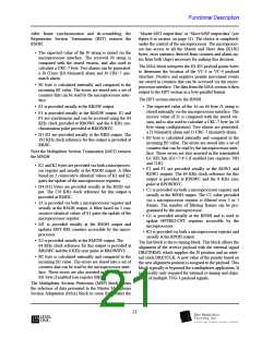
Receive Side Telecom Bus Timing
Source
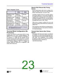
Table 4: Repeater Clocks
STM-0
MHICLK
In the Terminal mode, when receive re-timing is dis-
abled (see register 51H), the receive side telecom bus
timing is derived from the “recovered” clock.
STM-1
Multiplexer serial
clock input
Not used
Assuming an inactive LOS, the “recovered” clock is
derived from DHICLK in serial mode and DHBCLK
in parallel mode. During an active LOS condition, if
configured (see register 40H), the “recovered” clock is
derived from MHICLK in serial mode and MHBCLKI
in parallel mode (used as “blue” clocks).
(51.84 MHz)
Multiplexer paral-
lel clock input
MHBCLK
(6.48 MHz)
MHBCLK
(19.44 MHz)
Demultiplexer
DHICLK
Not used
serial clock input
(51.84 MHz)
When receive re-timing is enabled, the receive side
telecom bus timing is derived from the re-timing clock
(DRETCLK).
Demultiplexer par- DHBCLK
allel clock input (6.48 MHz)
DHBCLK
(19.44 MHz)
This arrangement of the SXT6051 providing both tim-
ing and data (at the receive telecom bus) is referred to
as co-directional timing.
1. DRETFRMI and DRETCLK are used when a re-timing func-
tion is implemented on the receive side.
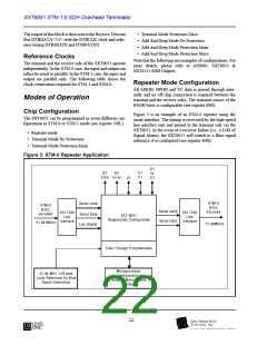
Terminal Mode Configuration (No
Protection)
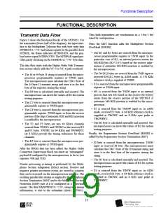
Transmit Side Telecom Bus Timing
Source
The transmit side telecom bus timing is provided by
the SXT6051. It is derived from the local clock refer-
ence (MHICLK in serial mode and MHBCLKI in par-
allel mode). This arrangement of the SXT6051
providing the timing and receiving the data (at the
transmit telecom bus) is referred to as
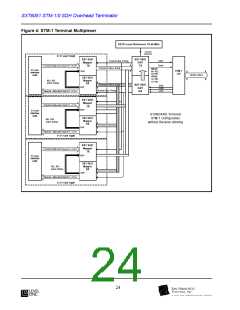
In Figure 4 the SXT6051 is used with the SXT6251 for the
implementation of an STM-1 terminal multiplexer. The
SXT6251 is a 21 E1 mapper designed to accommodate 21
E1 tributaries in a single chip. The SXT6051 and the
SXT6251 communicate via the Telecom Bus. In an STM-
0 configuration a single 21 E1 multiplexer is required. In an
STM-1 terminal multiplexer, three 21 E1 mappers are
required, sharing the telecom bus to implement a full
63xE1 MUX Telecom bus.
contra-directional timing.
23
l

 LevelOne [ LEVEL ONE ]