LTC3649
APPLICATIONS INFORMATION
Once the value for L is known, the type of inductor must
be selected. Core loss is very dependent on the material,
frequency and inductance selected. Higher inductance
reduces ripple. Unfortunately, increased inductance re-
quires more turns of wire and therefore copper losses
will increase.
optimization of the control loop behavior and provides
a DC-coupled and AC-filtered closed-loop response test
point. The DC step, rise time and settling at this test point
truly reflects these closed-loop responses. Assuming a
predominantly second order system, phase margin and/
or damping factor can be estimated using the percentage
of overshoot seen at this pin.
Ferrite materials have very low core losses and are pre-
ferred at high switching frequencies, so design goals can
minimizecopperlossandpreventingsaturation.However,
ferrite core material saturates “hard”, which means that
inductancecollapsesabruptlywhenthepeakdesigncurrent
is exceeded. This results in an abrupt increase in inductor
ripple current and consequent output voltage ripple. Do
not allow the core to saturate!
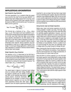
TheITHexternalcomponentnetworkshownintheFigure2
circuit will provide an adequate starting point for most
applications. The RC filter sets the dominant pole-zero
loop compensation. The values can be modified slightly
(from 0.5 to 2 times their suggested value) to optimize
transient response once the final PC layout is done and
the particular output capacitor type and value have been
determined. The output capacitors need to be selected
because their various types and values determine the
loop feedback factor gain and phase. An output current
pulse of 208 to 1008 of full load current having a rise
time of 1µs to 10µs will produce output voltage and ITH
pin waveforms that will give a sense of the overall loop
stability without breaking the feedback loop.
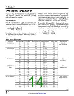
Different core materials and shapes will change the size/
currentandprice/currentrelationshipofaninductor.Toroid
or shielded pot cores in ferrite or permalloy materials are
small and don’t radiate much energy, but generally cost
more than powdered iron core inductors with similar
characteristics. The choice of which style inductor to use
mainly depends on the price versus size requirements
and any radiated field/EMI requirements. New designs for
surface mount inductors are available from Toko, Vishay,
NEC/Tokin, Cooper, TDK and Wurth Elektronik. Refer to
Table 1 for more details.
Switching regulators take several cycles to respond to
a step in load current. When a load step occurs, V
OUT
immediately shifts by an amount equal to the ΔI
•
.
LOAD
ESR, where ESR is the effective series resistance of C
OUT
ΔI
also begins to charge or discharge C
generat-
LOAD
OUT
Checking Transient Response
ing a feedback error signal used by the regulator to return
V
V
to its steady-state value. During this recovery time,
canbemonitoredforovershootorringingthatwould
OUT
OUT
The OPTI-LOOP external compensation allows the tran-
sient response to be optimized for a wide range of loads
and output capacitors via the ITH pin. This allows for
indicate a stability problem.
C
BOOST
0.1µF
L
1.5µH
V
IN
V
BOOST SW
IN
24V
V
+
OUT
RUN
V
OUT
3.3V
C
C
OUT
IN
22µF
47µF
LTC3649
×2
V
INTV
MODE/SYNC
SGND
INREG
CC
C
2.2µF
PGND
IMON
VCC
R
T
ISET
ITH
R
ITH
R
C
R
3k
R
C
T
SET
SET
IMON
IMON
100k
10nF
50k
10k
10nF
C
ITH
4.7nF
3649 F02
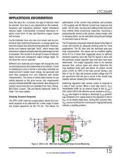
Figure 2. 24V to 3.3V, 1MHz Buck Regulator with Output Current Monitoring
3649fb
15
For more information www.linear.com/LTC3649

 Linear [ Linear ]