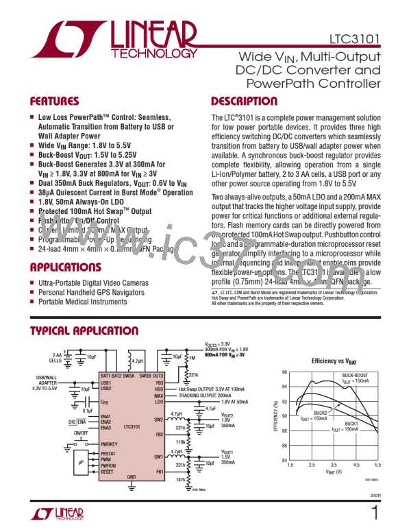
LTC3101
OPERATION
transient response of the converter. Increasing the value
of R2 generally leads to greater stability at the expense of
reduced transient response speed. Increasing the value of
R2 can yield substantial transient response improvement
in cases where the phase margin has been reduced due to
use of a small value output capacitor or a large inductance
(particularly with large boost step-up ratios). Conversely,
decreasing the value of R2 increases the loop bandwidth
which can improve the speed of the converter’s transient
response. This can be useful in improving the transient
response if a large value output capacitor is utilized. In
this case, the increased bandwidth created by decreasing
R2 is used to counteract the reduced converter bandwidth
caused by the large output capacitor.
Reverse Current Limit
A reverse current comparator on switch D monitors the
current entering the OUT3 pin. When this current exceeds
400mA (typical) switch D will be turned off for the re-
mainder of the switching cycle. This feature protects the
buck-boostconverterfromexcessivereversecurrentifthe
buck-boost output is held above the regulation voltage by
an external source.
Burst Mode Operation
With the PWM pin held low, the buck-boost converter
operatesutilizingavariablefrequencyswitchingalgorithm
designed to improve efficiency at light load and reduce
the standby current at zero load. In Burst Mode operation,
the inductor is charged with fixed peak amplitude current
pulses. These current pulses are repeated as often as
necessary to maintain the output regulation voltage. The
maximum output current, I
Burst Mode operation is dependent upon the input and
output voltage as given by the following formula:
Current Limit Operation
The buck-boost converter has two current limit circuits.
The primary current limit is an average current limit cir-
cuit which injects an amount of current into the feedback
node which is proportional to the extent that the switch A
(or A´) current exceeds the current limit value. Due to the
high gain of the feedback loop, the injected current forces
the error amplifier output to decrease until the average
current through switch A decreases approximately to the
current limit value. The average current limit utilizes the
error amplifier in an active state and thereby provides a
smoothrecoverywithlittleovershootoncethecurrentlimit
fault condition is removed. Since the current limit is based
on the average current through switch A (or A´), the peak
inductor current in current limit will have a dependency
on the duty cycle (i.e., on the input and output voltages)
in the overcurrent condition.
, which can be supplied in
MAX
0.15 • V
IN
IMAX
=
A
( )
V + VOUT
IN
If the buck-boost load exceeds the maximum Burst Mode
currentcapability,theoutputrailwillloseregulationandthe
power good comparator will indicate a fault condition.
InBurstModeoperation,theerroramplifierisnotusedbut
is instead placed in a low current standby mode to reduce
supply current and improve light load efficiency.
Internal Voltage Mode Soft-Start
The speed of the average current limit circuit is limited by
thedynamicsoftheerroramplifier. Onahardoutputshort,
itwouldbepossiblefortheinductorcurrenttoincreasesub-
stantially beyond current limit before the average current
limit circuit would react. For this reason, there is a second
current limit circuit which turns off switch A (and A´) if the
current ever exceeds approximately 165% of the average
current limit value. This provides additional protection in
the case of an instantaneous hard output short.
The buck-boost converter has an internal voltage mode
soft-start circuit with a nominal duration of 800ꢀs. The
converter remains in regulation during soft-start and will
therefore respond to output load transients that occur
during this time. In addition, the output voltage rise time
has minimal dependency on the size of the output capaci-
tor or load. During soft-start, the buck-boost converter is
forced into PWM mode operation regardless of the state
of the PWM pin.
3101f
19

 Linear [ Linear ]