LTC2309
APPLICATIONS INFORMATION
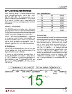
Table 2. Address Assignment
After power-up, the ADC initiates an internal reset
AD1
LOW
AD0
LOW
ADDRESS
0001000
0001001
0001010
0001011
0011000
0011001
0011010
0011011
0101000
cycle which sets the D word to all 0s (S/D = O/S =
IN
S0 = S1 = UNI = SLP = 0). A write operation may be
performedifthedefaultstateoftheADC’sconfiguration
is not desired. Otherwise, the ADC must be properly
addressed and followed by a Stop condition to initiate
a conversion.
LOW
FLOAT
HIGH
HIGH
FLOAT
LOW
LOW
FLOAT
FLOAT
FLOAT
HIGH
HIGH
HIGH
Initiating a New Conversion
LOW
FLOAT
HIGH
The LTC2309 awakens from either nap or sleep when
properly addressed for a read/write operation. A Stop
command may then be issued after performing the
read/write operation to trigger a new conversion.
Continuous Read
Issuing a Stop command after the 8th SCL clock pulse
of the address frame and before the completion of a
read/write operation will also initiate new conversion,
but the output result may not be valid due to lack of
adequate acquisition time (see Acquisition section).
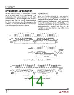
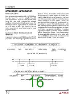
Inapplicationswherethesameinputchannelissampled
eachcycle,conversionscanbecontinuouslyperformed
and read without a write cycle (see Figure 9). The D
IN
word remains unchanged from the last value written
into the device. If the device has not been written to
since power-up, the D word defaults to all 0s (S/D =
IN
LTC2309 Address
O/S = S0 = S1 = UNI = SLP = 0). At the end of a read
operation, a Stop condition may be given to start a new
conversion. At the conclusion of the conversion cycle,
thenextresultmaybereadusingthemethoddescribed
above. If the conversion cycle is not concluded and a
valid address selects the device, the LTC2309 gener-
ates a NAK signal indicating the conversion cycle is in
progress.
The LTC2309 has two address pins (AD0 and AD1) that
may be tied high, low, or left floating to enable one of
9 possible addresses (see Table 2).
In addition to the configurable addresses listed in
Table 2, the LTC2309 also contains a global address
(1110111) which may be used for synchronizing mul-
2
tiple LTC2309s or other I C LTC230X SAR ADCs (see
Synchronizing Multiple LTC2309s with Global Address
Call section).
S 7-BIT ADDRESS R ACK READ P
S 7-BIT ADDRESS R ACK READ P
CONVERSION
NAP
DATA OUTPUT CONVERSION
NAP
DATA
OUTPUT
CONVERSION
2309 F09
Figure 9. Consecutive Reading with the Same Configuration
2309f
15

 Linear [ Linear ]