LTC2309
APPLICATIONS INFORMATION
2
Each device on the I C bus is recognized by a unique
Data Transferring
addressstoredinthedeviceandcanonlyoperateeither
as a transmitter or receiver, depending on the function
of the device. A device can also be considered as a
master or a slave when performing data transfers. A
master is the device which initiates a data transfer on
the bus and generates the clock signals to permit the
transfer. Devices addressed by the master are consid-
ered slaves.
2
After the Start condition, the I C bus is busy and data
transfercanbeginbetweenthemasterandtheaddressed
slave. Data is transferred over the bus in groups of
nine bits, one byte followed by one acknowledge (ACK)
bit. The master releases the SDA line during the ninth
SCL clock cycle. The slave device can issue an ACK by
pulling SDA low or issue a Not Acknowledge (NAK)
by leaving the SDA line high impedance (the external
The LTC2309 can only be addressed as a slave (see pull-up resistor will hold the line high). Change of data
Table 2). Once addressed, it can receive configuration only occurs while the SCL line is low.
bits(D word)ortransmitthelastconversionresult.The
IN
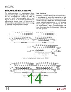
Data Format
serialclockline(SCL)isalwaysaninputtotheLTC2309
andtheserialdataline(SDA)isbidirectional.Thedevice
supports the standard mode and the fast mode for data
transfer speeds up to 400kbits/s (see Timing Diagram
After a Start condition, the master sends a 7-bit ad-
dress followed by a read/write (R/W) bit. The R/W
bit is 1 for a read request and 0 for a write request.
If the 7-bit address matches one of the LTC2309’s
9 pin-selectable addresses, the ADC is selected. When
the ADC is addressed during a conversion, it will not
2
section for definition of the I C timing).
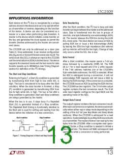
The Start and Stop Conditions
Referring to Figure 7, a Start (S) condition is generated acknowledge R/W requests and will issue a NAK by
by transitioning SDA from high to low while SCL is leavingtheSDAlinehigh. Iftheconversioniscomplete,
high. The bus is considered to be busy after the Start
condition. When the data transfer is finished, a Stop
the LTC2309 issues an ACK by pulling the SDA line low.
The LTC2309 has two registers. The 12-bit wide output
(P) condition is generated by transitioning SDA from register contains the last conversion result. The 6-bit
low to high while SCL is high. The bus is free after a wide input register configures the input MUX and the
Stop condition is generated. Start and Stop conditions operating mode of the ADC.
are always generated by the master.
Output Data Format
When the bus is in use, it stays busy if a Repeated
The output register contains the last conversion result.
Start (Sr) is generated instead of a Stop condition.
The Repeated Start timing is functionally identical to
the Start and is used for writing and reading from the
device before the initiation of a new conversion.
Aftereachconversioniscompleted,thedeviceautomati-
cally enters either nap or sleep mode depending on the
setting of the SLP bit (see Nap Mode and Sleep Mode
sections). When the LTC2309 is addressed for a read
operation, it acknowledges by pulling SDA low and acts
as a transmitter. The master/receiver can read up to two
bytes from the LTC2309. After a complete read opera-
tion of 2 bytes, a Stop condition is needed to initiate a
new conversion. The device will NAK subsequent read
operations while a conversion is being performed.
Start Condition
Stop Condition
SDA
SDA
SCL
S
P
2309 F07
SCL
Figure 7. Timing Diagrams of Start and Stop Conditions
2309f
13

 Linear [ Linear ]