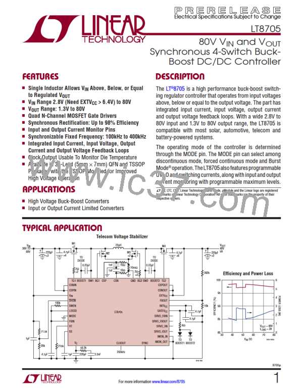
LT8705
APPLICATIONS INFORMATION
Select M3 and M4: With 12V output voltage we need
MOSFETs with 20V or higher rating.
Capacitors: A low ESR (5mΩ) capacitor network for C
is selected. In this mode, the maximum ripple is:
IN
V
IN(MAX) •I
The highest dissipation occurs in the boost region when
input voltage is minimum and output current is highest.
For switch M3 the dissipation is:
∆V
≅
OUT(MAX) •ESR
(BUCK,ESR)
VOUT(MIN)
25V •5A
2
P
= P + P
≅
∆V
≅
•5mΩ = 52mV
M3
I R
SWITCHING
(BUCK,ESR)
12V
V
– V • V
IN
OUT
(
)
OUT
assuming ESR dominates the ripple.
2
•I
•R
•ρ
τ
DS(ON)
OUT
2
V
IN
Having 5mΩ of ESR for the C
network sets the maxi-
OUT
mum output voltage ripple at:
t
RF2
2
+ V
•I
• f •
W
OUT
OUT
VOUT(MAX) •I
V
OUT(MAX) •ESR
IN
∆V
≅
(BOOST,ESR)
V
IN(MIN)
asdescribedinthePowerMOSFETSelectionandEfficiency
Considerations section.
12V •5A
∆V
≅
•5mΩ = 37.5mV
(BOOST,ESR)
8V
The maximum dissipation in switch M4 is:
assuming ESR dominates the ripple.
V
OUT(MAX)
2
P
≅
•I
•ρ •R
W
OUT
τ
DS(ON)
M4,BOOST
(
)
V
IN(MIN)
The Fairchild FDMS7672 can also be used for M3 and M4.
Assuming 20ns rise and fall times, the calculated power
loss at the minimum 8V input voltage is then 0.82W for
M3 and 0.39W for M4
Output Voltage: Output voltage is 12V. Select R
as
FBOUT2
20k. R
is:
FBOUT1
VOUT •RFBOUT2
RFBOUT1
=
1.207V
SelectR
as200k.BothR
andR
should
FBOUT1
FBOUT1
FBOUT2
have a tolerance of no more than 1%.
8705p
39
For more information www.linear.com/8705

 Linear [ Linear ]