LT8705
APPLICATIONS INFORMATION
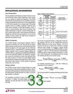
R Selection: Choose the R resistor for the free-running
Now calculate the maximum R
values in the boost
SENSE
T
T
oscillator frequency using:
and buck regions to be:
RSENSE(MAX,BOOST)
=
43,750
fOSC
43,750
350
RT =
–1 kΩ =
–1 = 124kΩ
2•VRSENSE(MAX,BOOST,MAX) •V
IN(MIN)
Ω
2•IOUT(MAX,BOOST) •VOUT(MIN) + ∆I
•V
IN(MIN)
(
) (
)
L(MAX,BOOST)
R
Selection: Start by calculating the maximum duty
SENSE
cycle in the boost region:
2•107mV •8V
=
= 11.4mΩ
2•5A •12V + 3.75A •8V
(
) (
)
V
IN(MIN)
DC
≅ 1–
•100%
(MAX,M3,BOOST)
V
OUT(MAX)
2•86mV
RSENSE(MAX,BUCK)
=
Ω
2•I
– ∆I
L(MIN,BUCK)
(
)
OUT(MAX,BUCK)
8V
= 1–
•100% = 33%
12V
2•86mV
=
= 18.2mΩ
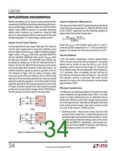
Next, from the Maximum Inductor Current Sense Voltage
vs Duty Cycle graph in the Typical Performance Charac-
teristics section:
2•5A –0.53A
(
)
Adding an additional 30% margin, choose R
11.4mΩ/1.3 = 8.7mΩ.
to be
SENSE
V
≅ 107mV
RSENSE(MAX,BOOST,MAX)
Inductor Selection: With R
known, we can now
SENSE
Next, estimate the maximum and minimum inductor cur-
rent ripple in the boost and buck regions respectively:
determine the minimum inductor value that will provide
adequate load current in the boost region using:
VOUT(MAX) •I
L(MIN1,BOOST)
≅
∆IL(MAX,BOOST)
≅
OUT(MAX,BOOST) A
100%
V
•
–0.5
IN(MIN)
DC(MAX,M3,BOOST)
100%
%Ripple
V
•
IN(MIN)
H
12V •5A
VRSENSE(MAX,BOOST,MAX) IOUT(MAX) •VOUT(MAX)
=
= 3.75A
2•f•
–
100%
40%
RSENSE
V
IN(MIN)
8V •
–0.5
33%
100%
107mV 5A •12V
8.7mV
I
8V •
∆IL(MIN,BUCK)
≅
OUT(MAX,BUCK) A
=
= 0.8µH
100%
10%
–0.5
2•350kHz •
–
8V
5A
100%
10%
=
= 0.53A
–0.5
8705p
37
For more information www.linear.com/8705

 Linear [ Linear ]