LT8705
APPLICATIONS INFORMATION
If the inductor value is already known then ∆I
constant(frequency=350kHz,inductance=10μH,R
=
L(MIN,BUCK)
SENSE
can be calculated as follows:
10mΩ).Thisgraphisnormalizedandaccountsforchanges
inmaximumcurrentduetotheslopecompensationramps
and the effects of changing ripple current. The curve is
theoretical, but can be used as a guide to predict relative
changes in maximum output and inductor current over a
DC
(MIN,M2,BUCK)
•VOUT(MIN)
100%
∆IL(MIN,BUCK
=
A
)
f•L
range of V /V
voltages.
IN OUT
where:
DC
is the minimum duty cycle percentage
(MIN,M2,BUCK)
in the buck region as calculated previously.
Reverse Current Limit
When the forced continuous mode is selected (MODE
pin low), inductor current is allowed to reverse directions
f is the switching frequency
and flow from the V
side to the V side. This can lead
OUT
IN
L is the inductance of the main inductor
After the inductor ripple current is known, the maximum
to current sinking from the output and being forced into
the input. The reverse current is at a maximum magni-
allowed R
follows:
in the buck region can be calculated as
SENSE
tude when V is lowest. The graph of Minimum Inductor
C
Current Sense Voltage in FCM in the Typical Performance
Characteristicssectioncanhelptodeterminethemaximum
reverse current capability.
2•86mV
RSENSE(MAX,BUCK)
=
2•I
– ∆I
L(MIN,BUCK)
(
)
OUT(MAX,BUCK)
Inductor Selection
Final R
Value: The final R
value should be
SENSE(MAX,BUCK)
SENSE
lowerthanbothR
SENSE
For high efficiency, choose an inductor with low core
loss, such as ferrite. Also, the inductor should have low
andR
.
SENSE(MAX,BOOST)
A margin of 30% or more is recommended.
2
DC resistance to reduce the I R losses, and must be able
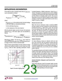
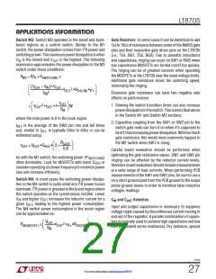
Figure 8 shows approximately how the maximum output
current and maximum inductor current would vary with
to handle the peak inductor current without saturating. To
minimize radiated noise, use a toroid, pot core or shielded
bobbin inductor.
V /V
IN OUT
while all other operating parameters remain
1.0
The operating frequency and inductor selection are inter-
related in that higher operating frequencies allow the use
of smaller inductor and capacitor values. The following
sectionsdiscussseveralcriteriatoconsiderwhenchoosing
an inductor value. For optimal performance, choose an
inductor that meets all of the following criteria.
0.8
MAXIMUM
INDUCTOR
CURRENT
0.6
MAXIMUM
OUTPUT
CURRENT
0.4
Inductor Selection: Adequate Load Current in the
Boost Region
0.2
0
Small value inductors result in increased ripple currents
andthus,duetothelimitedpeakinductorcurrent,decrease
the maximum average current that can be provided to the
10
0.1
1
V
/V
(V/V)
IN OUT
8705 F08
load (I ) while operating in the boost region.
OUT
Figure 8. Currents vs VIN/VOUT Ratio
8705p
23
For more information www.linear.com/8705

 Linear [ Linear ]