LT1576/LT1576-5
U
W U U
APPLICATIONS INFORMATION
How Do I Test Loop Stability?
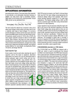
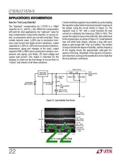
I check switching regulator loop stability by pulse loading
the regulator output while observing transient response at
the output, using the circuit shown in Figure 13. The
regulator loop is “hit” with a small transient AC load
current at a relatively low frequency, 50Hz to 1kHz. This
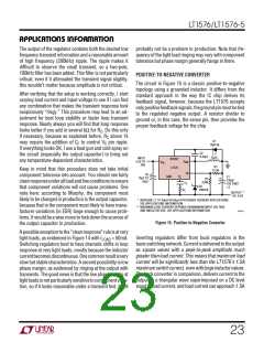
causes the output to jump a few millivolts, then settle back
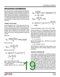
totheoriginalvalue,asshowninFigure14. Awellbehaved
loop will settle back cleanly, whereas a loop with poor
phase or gain margin will “ring” as it settles. The number
ofringsindicatesthedegreeofstability, andthefrequency
of the ringing shows the approximate unity-gain fre-
quency of the loop. Amplitude of the signal is not particu-
larlyimportant, aslongastheamplitudeisnotsohighthat
the loop behaves nonlinearly.
The “standard” compensation for LT1576 is a 100pF
capacitor for CC, with RC = 0Ω. While this compensation
will work for most applications, the “optimum” value for
loop compensation components depends, to various ex-
tent, on parameters which are not well controlled. These
include inductor value (±30% due to production toler-
ance, load current and ripple current variations), output
capacitance (±20%to±50%duetoproductiontolerance,
temperature, aging and changes at the load), output
capacitor ESR (±200% due to production tolerance, tem-
perature and aging), and finally, DC input voltage and
output load current. This makes it important for the
designer to check out the final design to ensure that it is
“robust” and tolerant of all these variations.
RIPPLE FILTER
TO X1
OSCILLOSCOPE
PROBE
470Ω
4.7k
SWITCHING
REGULATOR
+
100µF TO
1000µF
3300pF
330pF
50Ω
ADJUSTABLE
INPUT SUPPLY
ADJUSTABLE
DC LOAD
TO
OSCILLOSCOPE
SYNC
100Hz TO 1kHz
100mV TO 1V
P-P
1576 F13
Figure 13. Loop Stability Test Circuit
V
OUT AT
IOUT = 500mA
BEFORE FILTER
V
OUT AT
IOUT = 500mA
AFTER FILTER
VOUT AT
IOUT = 50mA
AFTER FILTER
LOAD PULSE
THROUGH 50Ω
f ≈ 780Hz
10mV/DIV
5A/DIV
0.2ms/DIV
1576 F14
Figure 14. Loop Stability Check
22

 Linear [ Linear ]