LT1576/LT1576-5
U
W U U
APPLICATIONS INFORMATION
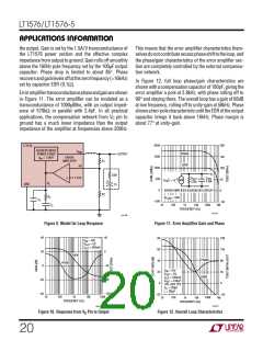
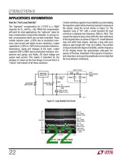
Analog experts will note that around 7kHz, phase dips
close to the zero phase margin line. This is typical of
switching regulators, especially those that operate over a
wide range of loads. This region of low phase is not a
problem as long as it does not occur near unity-gain. In
practice, the variability of output capacitor ESR tends to
dominate all other effects with respect to loop response.
Variations in ESR will cause unity-gain to move around,
but at the same time phase moves with it so that adequate
phase margin is maintained over a very wide range of ESR
(≥ ±3:1).
subharmonic switching occurs, as evidenced by alternat-
ing pulse widths seen at the switch node. In more severe
cases,theregulatorsquealsorhissesaudiblyeventhough
the output voltage is still roughly correct. None of this will
show on a theoretical Bode plot because Bode is an
amplitude insensitive analysis. Tests have shown that if
ripple voltage on the VC is held to less than 100mVP-P, the
LT1576 will be well behaved. The formula below will give
an estimate of VC ripple voltage when RC is added to the
loop, assuming that RC is large compared to the reactance
of CC at 200kHz.
What About a Resistor in the Compensation Network?
R G
V − V
ESR 1.21
( )(
)(
)(
)(
)
C
MA IN
OUT
V
=
C RIPPLE
It is common practice in switching regulator design to add
a “zero” to the error amplifier compensation to increase
loop phase margin. This zero is created in the external
network in the form of a resistor (RC) in series with the
compensation capacitor. Increasing the size of this resis-
tor generally creates better and better loop stability, but
there are two limitations on its value. First, the combina-
tion of output capacitor ESR and a large value for RC may
cause loop gain to stop rolling off altogether, creating a
gain margin problem. An approximate formula for RC
where gain margin falls to zero is:
(
)
V
L f
(
)( )( )
IN
GMA = Error amplifier transconductance (1000µMho)
If a computer simulation of the LT1576 showed that a
seriescompensationresistorof15kgavebestoverallloop
response, with adequate gain margin, the resulting VC pin
ripple voltage with VIN = 10V, VOUT = 5V, ESR = 0.1Ω,
L = 30µH, would be:
15k 1•10−3 10 − 5 0.1 1.21
(
)
(
)( )(
)
(
)
VC(RIPPLE
=
= 0.151V
)
10 30•10−6 200•103
( )
(
)(
)
V
OUT
R Loop Gain = 1 =
(
)
C
This ripple voltage is high enough to possibly create
subharmonic switching. In most situations a compromise
value (<10k in this case) for the resistor gives acceptable
phase margin and no subharmonic problems. In other
cases, the resistor may have to be larger to get acceptable
phaseresponse, andsomemeansmustbeusedtocontrol
ripple voltage at the VC pin. The suggested way to do this
istoaddacapacitor(CF)inparallelwiththeRC/CC network
on the VC pin. Pole frequency for this capacitor is typically
set at one-fifth of switching frequency so that it provides
significant attenuation of switching ripple, but does not
addunacceptablephaseshiftatloopunity-gainfrequency.
With RC = 15k,
G
(
G
ESR 1.21
)(
)(
)(
)
MP MA
GMP = Transconductance of power stage = 1.5A/V
GMA = Error amplifier transconductance = 1(10–3)
ESR = Output capacitor ESR
1.21 = Reference voltage
With VOUT = 5V and ESR = 0.1Ω, a value of 27.5k for RC
would yield zero gain margin, so this represents an upper
limit. There is a second limitation however which has
nothing to do with theoretical small signal dynamics. This
resistor sets high frequency gain of the error amplifier,
including the gain at the switching frequency. If switching
frequency gain is high enough, output ripple voltage will
appear at the VC pin with enough amplitude to muck up
proper operation of the regulator. In the marginal case,
5
)( )(
5
CF =
=
= 265pF
2π 200•103 15k
2π f R
(
)
C
(
)
(
)
21

 Linear [ Linear ]