LT1576/LT1576-5
U
W U U
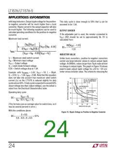
APPLICATIONS INFORMATION
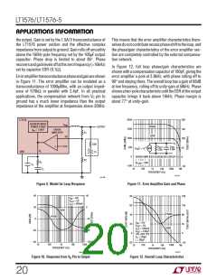
the output. Gain is set by the 1.5A/V transconductance of
the LT1576 power section and the effective complex
impedance from output to ground. Gain rolls off smoothly
above the 160Hz pole frequency set by the 100µF output
capacitor. Phase drop is limited to about 85°. Phase
recoversandgainlevelsoffatthezerofrequency(≈16kHz)
set by capacitor ESR (0.1Ω).
This means that the error amplifier characteristics them-
selvesdonotcontributeexcessphaseshifttotheloop,and
the phase/gain characteristics of the error amplifier sec-
tion are completely controlled by the external compensa-
tion network.
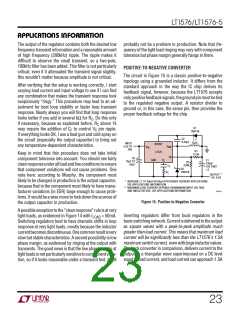
In Figure 12, full loop phase/gain characteristics are
shownwithacompensationcapacitorof100pF, givingthe
error amplifier a pole at 2.8kHz, with phase rolling off to
90° and staying there. The overall loop has a gain of 66dB
at low frequency, rolling off to unity-gain at 58kHz. Phase
showsatwo-polecharacteristicuntiltheESRoftheoutput
capacitor brings it back above 16kHz. Phase margin is
about 77° at unity-gain.
Erroramplifiertransconductancephaseandgainareshown
in Figure 11. The error amplifier can be modeled as a
transconductance of 1000µMho, with an output imped-
ance of 570kΩ in parallel with 2.4pF. In all practical
applications, the compensation network from VC pin to
ground has a much lower impedance than the output
impedance of the amplifier at frequencies above 200Hz.
2000
1500
1000
500
200
150
100
50
LT1576
CURRENT MODE
POWER STAGE
V
SW
FB
PHASE
GAIN
OUTPUT
ERROR
g
= 1.5A/V
m
AMPLIFIER
R1
R2
–
V
C
ESR
C1
+
1.21V
C
R
OUT
2.4pF
–3
OUT
570k
V
1 × 10
(
)
+
FB
V
C
GND
0
ERROR AMPLIFIER EQUIVALENT CIRCUIT
= 50Ω
0
R
C
R
LOAD
C
F
–500
–50
C
10
100
1k
10k
100k
1M
C
FREQUENCY (Hz)
1576 F11
1576 F09
Figure 9. Model for Loop Response
Figure 11. Error Amplifier Gain and Phase
40
20
0
40
80
60
180
135
90
V
V
= 10V
IN
= 5V
OUT
OUT
I
= 500mA
0
GAIN
PHASE
GAIN
40
PHASE
–40
–80
–120
V
V
= 10V
IN
20
45
= 5V
OUT
OUT
OUT
I
= 500mA
= 100µF
–20
–40
C
0
0
10V, AVX TPS
C
= 100pF
C
L = 30µH
–20
–45
1M
10
100
1k
FREQUENCY (Hz)
10k
100k
10
100
1k
10k
100k
FREQUENCY (Hz)
1576 F12
1576 F07
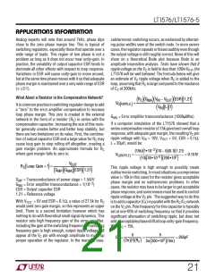
Figure 10. Response from VC Pin to Output
Figure 12. Overall Loop Characteristics
20

 Linear [ Linear ]