LT1576/LT1576-5
U
W U U
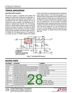
APPLICATIONS INFORMATION
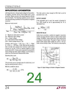
inductor is therefore typically based on ensuring that peak
switch current rating is not exceeded. This gives the
lowest value of inductance that can be used, but in some
cases (lower output load currents) it may give a value that
creates unnecessarily high output ripple voltage. A com-
promise value is often chosen that reduces output ripple.
As you can see from the graph, large inductors will not
give arbitrarily low ripple, but small inductors can give
high ripple.
2
2
)
5.5 1.5
(
) (
I
=
= 0.38A
CONT
4 5.5 + 5 5.5 +5 +0.5
(
)(
)
This says that discontinuous mode can be used and the
minimum inductor needed is found from:
2 5 0.25
( )(
)
L
=
= 5.6µH
MIN
The difficulty in calculating the minimum inductor size
needed is that you must first know whether the switcher
will be in continuous or discontinuous mode at the critical
point where switch current is 1.5A. The first step is to use
the following formula to calculate the load current where
the switcher must use continuous mode. If your load
current is less than this, use the discontinuous mode
formula to calculate minimum inductor needed. If load
current is higher, use the continuous mode formula.
2
)
3
200• 10 1.5
(
Inpractice,theinductorshouldbeincreasedbyabout30%
over the calculated minimum to handle losses and varia-
tionsinvalue. Thissuggestsaminimuminductorof7.3µH
for this application, but looking at the ripple voltage chart
showsthatoutputripplevoltagecouldbereducedbyafac-
toroftwobyusinga30µHinductor.Thereisnoruleofthumb
heretomakeafinaldecision.Ifmodestrippleisneededand
the larger inductor does the trick, go for it. If ripple is non-
critical use the smaller inductor. If ripple is extremely criti-
cal, a second filter may have to be added in any case, and
the lower value of inductance can be used. Keep in mind
thattheoutputcapacitoristheothercriticalfactorindeter-
mining output ripple voltage. Ripple shown on the graph
(Figure 16) is with a capacitor’s ESR of 0.1Ω. This is rea-
sonableforAVXtypeTPS“D”or“E”sizesurfacemountsolid
tantalumcapacitors,butthefinalcapacitorchosenmustbe
looked at carefully for ESR characteristics.
Output current where continuous mode is needed:
2
V
2 I
(
IN) ( P)
ICONT
=
4 V + V
V + V + V
IN OUT F
(
OUT)(
)
IN
Minimum inductor discontinuous mode:
2 V
I
(
OUT)( OUT
f I
)
LMIN
=
2
( )( P)
Minimum inductor continuous mode:
V
V
OUT
( )(
)
IN
LMIN
=
V
+ VF
(
)
OUT
2 f V + V
I −I
1+
( )(
)
IN
OUT
P
OUT
V
IN
For the example above, with maximum load current of
0.25A:
25

 Linear [ Linear ]