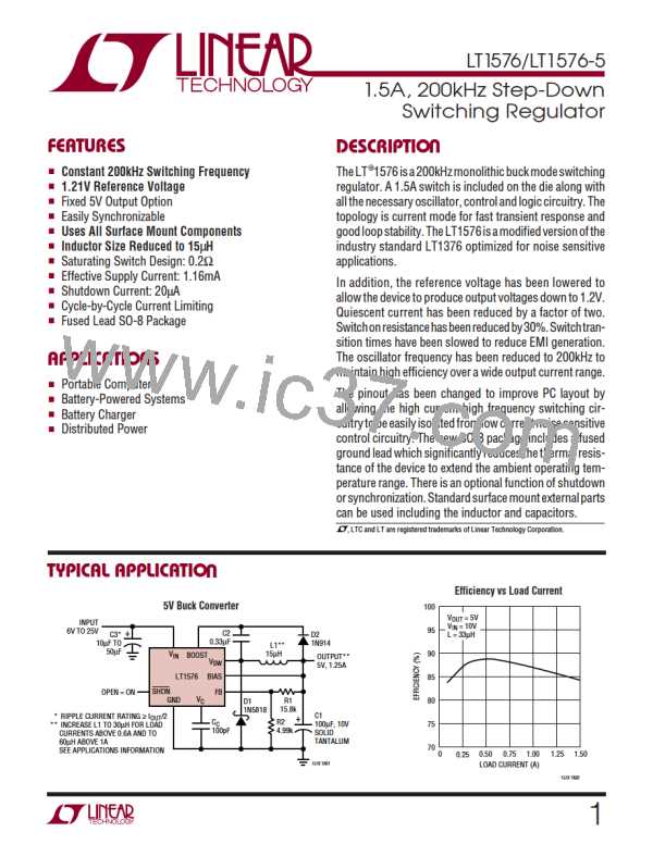
LT1576/LT1576-5
U
W U U
APPLICATIONS INFORMATION
Ripple Current in the Input and Output Capacitors
Diode Current
Positive-to-negativeconvertershavehighripplecurrentin
both the input and output capacitors. For long capacitor
lifetime, the RMS value of this current must be less than
the high frequency ripple current rating of the capacitor.
The following formula will give an approximate value for
RMS ripple current. This formula assumes continuous
mode and large inductor value. Small inductors will give
somewhat higher ripple current, especially in discontinu-
ous mode. The exact formulas are very complex and
appear in Application Note 44, pages 30 and 31. For our
purposes here I have simply added a fudge factor (ff). The
value for ff is about 1.2 for higher load currents and
L ≥10µH. It increases to about 2.0 for smaller inductors at
lower load currents.
Average diodecurrentisequaltoloadcurrent. Peak diode
current will be considerably higher.
Peak diode current:
Continuous Mode =
V + V
V
V
(
)
(
)(
)
IN
OUT
IN OUT
I
+
OUT
V
2 L f V + V
( )( )(
IN
)
IN
OUT
2 I
(
V
OUT
)(
)
OUT
Discontinuous Mode =
L f
( )( )
Keep in mind that during start-up and output overloads,
average diode current may be much higher than with
normalloads.Careshouldbeusedifdiodesratedlessthan
1A are used, especially if continuous overload conditions
must be tolerated.
VOUT
Capacitor IRMS = ff I
( )( OUT
)
V
IN
ff = Fudge factor (1.2 to 2.0)
26

 Linear [ Linear ]