LT3694/LT3694-1
APPLICATIONS INFORMATION
where f is the switching frequency of the LT3694 and L
is the value of the inductor. The peak inductor and switch
This analysis is valid for continuous mode operation
(I > I /2). For details of maximum output current in
OUT
LIM
current is:
discontinuous mode operation, see the Linear Technol-
∆IL
2
ogy Application Note 44. Finally, for duty cycles greater
ISWPK = ILPK = IOUT
+
than 50% (V /V > 0.5), a minimum inductance is
OUT IN
requiredtoavoidsubharmonicoscillations.Thisminimum
To maintain output regulation, this peak current must be
inductance is:
less than the LT3694’s switch current limit, I . I is at
LIM LIM
(VOUT + VF )
2A • fSW
least 3.5A at low duty cycles (0.1) and decreases linearly
LMIN
with L
=
to 2.8A at DC = 0.8.
The minimum inductance can now be calculated as:
in μH and f in MHz. A detailed discussion
MIN
SW
of subharmonic oscillations can be found in the Linear
Technology Application Note 19.
VOUT + VF
ILIM − IOUT
1− DCMIN
2• f
LMIN
=
•
Input Capacitor Selection
However, it’s generally better to use an inductor larger
than the minimum value. The minimum inductor has large
ripple currents which increase core losses and require
large output capacitors to keep output voltage ripple low.
Bypass the input of the LT3694 circuit with a ceramic
capacitor of X7R or X5R type. Y5V types have poor
performance over temperature and applied voltage, and
should not be used. A 4.7µF to 22μF ceramic capacitor
is adequate to bypass the LT3694 and will easily handle
the ripple current. Use a 22µF capacitor with f between
250kHz and 800kHz. Use a 10µF capacitor with f be-
tween 800kHz and 1.6MHz. Use a 4.7µF capacitor above
1.6MHz. Always check for sufficient margin by reducing
thecapacitorvalueuntilthedropoutincreasesby>500mV.
If the input power source has high impedance, or there
is significant inductance due to long wires or cables,
additional bulk capacitance may be necessary. This
can be provided with a lower performance electrolytic
capacitor.
Select an inductor greater than L
that keeps the ripple
MIN
current below 30% of I
.
LIM
SW
For input voltages greater than 30V, use an inductor with
a saturation current of 6A or greater and an inductance
value of 3.3µH or greater.
SW
Theinductor’sRMScurrentratingmustbegreaterthanthe
maximum load current and its saturation current should
be greater than I . For highest efficiency, the series
LPK
resistance (DCR) should be less than 0.1Ω. Table 2 lists
several vendors and types that are suitable.
Table 2. Inductors
INDUCTANCE
RANGE (µH)
CURRENT
RANGE (A)
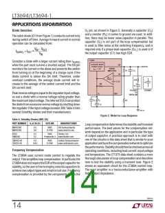
Step-down regulators draw current from the input sup-
ply in pulses with very fast rise and fall times. The input
capacitor is required to reduce the resulting voltage
ripple at the LT3694 and to force this very high frequency
switching current into a tight local loop, minimizing EMI.
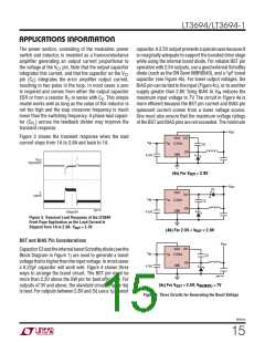
A 10μF capacitor is capable of this task, but only if it is
placed close to the LT3694 and the catch diode (see the
PCB Layout section). A second precaution regarding the
ceramic input capacitor concerns the maximum input
voltage rating of the LT3694. A ceramic input capacitor
combined with trace or cable inductance forms a high
SERIES
MANUFACTURER
WE-HC
1 to 6.5
6 to 15
Würth Elektronik
www.we-online.com
MSS1048
CDRH103R
VLF
0.8 to 8
4 to 8
Coilcraft
www.coilcraft.com
0.8 to 10
2.2 to 10
2.8 to 8.3
3.8 to 7.7
Sumida
www.sumida.com
TDK
www.component.tdk.
com
IHLP-2525CZ-11
1 to 10
2.5 to 9.5
Vishay
www.vishay.com
36941fb
12

 Linear [ Linear ]