LTC3787
APPLICATIONS INFORMATION
C and C
Selection
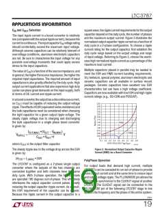
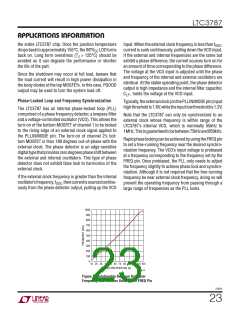
squarewave,theripplecurrentrequirementsfortheoutput
capacitor depend on the duty cycle, the number of phases
and the maximum output current. Figure 3 illustrates the
normalized output capacitor ripple current as a function of
duty cycle in a 2-phase configuration. To choose a ripple
current rating for the output capacitor, first establish the
duty cycle range based on the output voltage and range
of input voltage. Referring to Figure 3, choose the worst-
case high normalized ripple current as a percentage of the
maximum load current.
IN
OUT
The input ripple current in a boost converter is relatively
low(comparedwiththeoutputripplecurrent),becausethis
currentiscontinuous.TheinputcapacitorC voltagerating
IN
should comfortably exceed the maximum input voltage.
Although ceramic capacitors can be relatively tolerant of
overvoltage conditions, aluminum electrolytic capacitors
are not. Be sure to characterize the input voltage for any
possible overvoltage transients that could apply excess
stress to the input capacitors.
Multiple capacitors placed in parallel may be needed to
meet the ESR and RMS current handling requirements.
Dry tantalum, special polymer, aluminum electrolytic and
ceramic capacitors are all available in surface mount
packages. Ceramic capacitors have excellent low ESR
characteristics but can have a high voltage coefficient.
Capacitors are now available with low ESR and high ripple
current ratings (e.g., OS-CON and POSCAP).
ThevalueofC isafunctionofthesourceimpedance, and
IN
ingeneral,thehigherthesourceimpedance,thehigherthe
required input capacitance. The required amount of input
capacitance is also greatly affected by the duty cycle. High
output current applications that also experience high duty
cycles can place great demands on the input supply, both
in terms of DC current and ripple current.
Inaboostconverter,theoutputhasadiscontinuouscurrent,
so C
must be capable of reducing the output voltage
3.25
3.00
2.75
2.50
2.25
2.00
1.75
1.50
1.25
1.00
0.75
0.50
0.25
0
OUT
ripple.TheeffectsofESR(equivalentseriesresistance)and
the bulk capacitance must be considered when choosing
the right capacitor for a given output ripple voltage. The
steady ripple voltage due to charging and discharging
the bulk capacitance in a single phase boost converter
is given by:
1-PHASE
IOUT(MAX) •(VOUT − V
)
IN(MIN)
2-PHASE
VRIPPLE
=
V
COUT • VOUT • f
0.4 0.5
DUTY CYCLE OR (1-V /V
0.1 0.2 0.3
0.6 0.7 0.8 0.9
)
IN OUT
where C
is the output filter capacitor.
3787 F03
OUT
Figure 3. Normalized Output Capacitor Ripple
Current (RMS) for a Boost Converter
The steady ripple due to the voltage drop across the ESR
is given by:
ΔV
= I
• ESR
ESR
L(MAX)
PolyPhase Operation
The LTC3787 is configured as a 2-phase single output
converter where the outputs of the two channels are
connected together and both channels have the same
duty cycle. With 2-phase operation, the two channels
are operated 180 degrees out-of-phase. This effectively
interleaves the output capacitor current pulses, greatly
reducing the output capacitor ripple current. As a result,
the ESR requirement of the capacitor can be relaxed.
Because the ripple current in the output capacitor is a
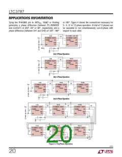
For output loads that demand high current, multiple
LTC3787s can be cascaded to run out-of-phase to provide
more output current and at the same time to reduce input
and output voltage ripple. The PLLIN/MODE pin allows the
LTC3787 to synchronize to the CLKOUT signal of another
LTC3787. The CLKOUT signal can be connected to the
PLLIN/MODE pin of the following LTC3787 stage to line
up both the frequency and the phase of the entire system.
3787fc
19

 Linear Systems [ Linear Systems ]