LTC3787
APPLICATIONS INFORMATION
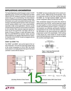
Sense Resistor Current Sensing
Inductor DCR Sensing
A typical sensing circuit using a discrete resistor is shown
For applications requiring the highest possible efficiency
at high load currents, the LTC3787 is capable of sensing
the voltage drop across the inductor DCR, as shown in
Figure 2b. The DCR of the inductor can be less than 1mΩ
for high current inductors. In a high current application
requiring such an inductor, conduction loss through a
sense resistor could reduce the efficiency by a few percent
compared to DCR sensing.
in Figure 2a. R
output current.
is chosen based on the required
SENSE
The current comparator has a maximum threshold
V
. When the ILIM pin is grounded, floating or
CC
SENSE(MAX)
tied to INTV , the maximum threshold is set to 50mV,
75mV or 100mV, respectively. The current comparator
threshold sets the peak of the inductor current, yielding
a maximum average inductor current, I
, equal to the
If the external R1||R2 • C1 time constant is chosen to be
exactly equal to the L/DCR time constant, the voltage drop
across the external capacitor is equal to the drop across
theinductorDCRmultipliedbyR2/(R1+R2).R2scalesthe
voltage across the sense terminals for applications where
the DCR is greater than the target sense resistor value.
To properly dimension the external filter components, the
DCR of the inductor must be known. It can be measured
using a good RLC meter, but the DCR tolerance is not
always the same and varies with temperature. Consult
the manufacturers’ data sheets for detailed information.
MAX
peak value less half the peak-to-peak ripple current, ΔI .
L
To calculate the sense resistor value, use the equation:
VSENSE(MAX)
RSENSE
=
ΔIL
IMAX
+
2
The actual value of I
required output current I
using:
for each channel depends on the
OUT(MAX)
MAX
and can be calculated
I
⎛
⎞
⎛
⎞
VOUT
OUT(MAX)
Using the inductor ripple current value from the induct-
or value calculation section, the target sense resistor
value is:
IMAX
=
•
⎜
⎟
⎜
⎟
2
V
⎝
⎠
⎝
⎠
IN
When using the controller in low V and very high voltage
IN
VSENSE(MAX)
output applications, the maximum inductor current and
correspondingly the maximum output current level will
be reduced due to the internal compensation required to
meet stability criterion for boost regulators operating at
greater than 50% duty factor. A curve is provided in the
Typical Performance Characteristics section to estimate
this reduction in peak inductor current level depending
upon the operating duty factor.
RSENSE(EQUIV)
=
ΔIL
IMAX
+
2
To ensure that the application will deliver full load current
over the full operating temperature range, choose the
minimum value for the maximum current sense threshold
(V
).
SENSE(MAX)
Next, determine the DCR of the inductor. Where provided,
use the manufacturer’s maximum value, usually given at
20°C. Increase this value to account for the temperature
coefficient of resistance, which is approximately 0.4%/°C.
Aconservativevalueforthemaximuminductortemperature
(T
) is 100°C.
L(MAX)
3787fc
16

 Linear Systems [ Linear Systems ]