LTC3787
APPLICATIONS INFORMATION
EXTV remains above 4.55V. The EXTV LDO attempts
output voltage: V
= V
+ V
. The value of
INTVCC
CC
CC
BOOST
OUT
to regulate the INTV voltage to 5.4V, so while EXTV
the boost capacitor C needs to be 100 times that of the
CC
CC
CC
CC
B
is less than 5.4V, the LDO is in dropout and the INTV
total input capacitance of the topside MOSFET(s). The
voltage is approximately equal to EXTV . When EXTV
reverse breakdown of the external Schottky diode must
CC
is greater than 5.4V, up to an absolute maximum of 6V,
be greater than V
.
OUT(MAX)
INTV is regulated to 5.4V.
CC
The external diode D can be a Schottky diode or silicon
B
Significant thermal gains can be realized by powering
diode,butineithercaseitshouldhavelowleakageandfast
recovery. Paycloseattentiontothereverseleakageathigh
temperatures where it generally increases substantially.
INTV from an external supply. Tying the EXTV pin
CC
CC
to a 5V supply reduces the junction temperature in the
previous example from 125°C to 79°C in a QFN package:
Each of the topside MOSFET drivers includes an internal
chargepumpthatdeliverscurrenttothebootstrapcapaci-
tor from the BOOST pin. This charge current maintains
the bias voltage required to keep the top MOSFET on
continuously during dropout/overvoltage conditions. The
Schottky/silicon diodes selected for the topside drivers
shouldhaveareverseleakagelessthantheavailableoutput
current the charge pump can supply. Curves displaying
the available charge pump current under different operat-
ing conditions can be found in the Typical Performance
Characteristics section.
T = 70°C + (32mA)(5V)(43°C/W) = 77°C
J
and from 125°C to 74°C in an SSOP package:
T = 70°C + (15mA)(5V)(90°C/W) = 77°C
J
If more current is required through the EXTV LDO than
CC
is specified, an external Schottky diode can be added be-
tween the EXTV and INTV pins. Make sure that in all
CC
CC
cases EXTV ≤ VBIAS (even at start-up and shutdown).
CC
The following list summarizes possible connections for
EXTV :
CC
A leaky diode D in the boost converter can not only
B
EXTV Grounded.ThiswillcauseINTV tobepowered
CC
CC
prevent the top MOSFET from fully turning on but it can
fromtheinternal5.4Vregulatorresultinginanefficiency
also completely discharge the bootstrap capacitor C and
B
penalty at high input voltages.
create a current path from the input voltage to the BOOST
pin to INTV . This can cause INTV to rise if the diode
EXTV Connected to an External Supply. If an external
CC
CC
CC
leakage exceeds the current consumption on INTV .
supply is available in the 5V to 6V range, it may be used
CC
This is particularly a concern in Burst Mode operation
to provide power. Ensure that EXTV is always lower
CC
where the load on INTV can be very small. The external
than VBIAS.
CC
Schottky or silicon diode should be carefully chosen such
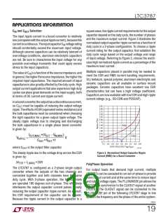
Topside MOSFET Driver Supply (C , D )
that INTV never gets charged up much higher than its
B
B
CC
normal regulation voltage.
ExternalbootstrapcapacitorsC connectedtotheBOOST
B
pins supply the gate drive voltages for the topside
Fault Conditions: Overtemperature Protection
MOSFETs. Capacitor C in the Block Diagram is charged
B
At higher temperatures, or in cases where the internal
power dissipation causes excessive self heating on-chip
though external diode D from INTV when the SW pin
B
CC
is low. When one of the topside MOSFETs is to be turned
(such as an INTV short to ground), the overtemperature
on, the driver places the C voltage across the gate and
CC
B
shutdown circuitry will shut down the LTC3787. When the
sourceofthedesiredMOSFET.ThisenhancestheMOSFET
junction temperature exceeds approximately 170°C, the
and turns on the topside switch. The switch node volt-
overtemperaturecircuitrydisablestheINTV LDO,causing
age, SW, rises to V
and the BOOST pin follows. With
CC
OUT
the INTV supply to collapse and effectively shut down
the topside MOSFET on, the boost voltage is above the
CC
3787fc
22

 Linear Systems [ Linear Systems ]