LTC3787
APPLICATIONS INFORMATION
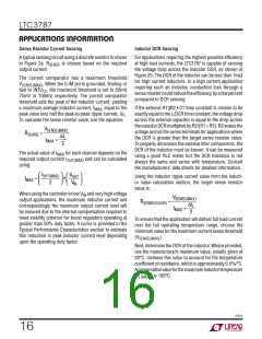
To scale the maximum inductor DCR to the desired sense
resistor value, use the divider ratio:
Inductor Value Calculation
The operating frequency and inductor selection are in-
terrelated in that higher operating frequencies allow the
use of smaller inductor and capacitor values. Why would
anyone ever choose to operate at lower frequencies with
larger components? The answer is efficiency. A higher
frequency generally results in lower efficiency because
of MOSFET gate charge and switching losses. Also, at
higher frequency the duty cycle of body diode conduction
is higher, which results in lower efficiency. In addition to
this basic trade-off, the effect of inductor value on ripple
currentandlowcurrentoperationmustalsobeconsidered.
RSENSE(EQUIV)
RD =
DCRMAX at TL(MAX)
C1 is usually selected to be in the range of 0.1μF to 0.47μF.
ThisforcesR1||R2toaround2k, reducingerrorthatmight
have been caused by the SENSE pin’s 1μA current.
–
The equivalent resistance R1|| R2 is scaled to the room
temperature inductance and maximum DCR:
L
R1||R2 =
(DCR at 20°C)•C1
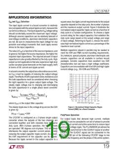
The inductor value has a direct effect on ripple current.
The inductor ripple current ΔI decreases with higher
L
The sense resistor values are:
inductance or frequency and increases with higher V :
IN
R1•RD
1−RD
R1||R2
RD
⎛
⎞
R1=
; R2 =
V
f •L
V
IN
VOUT
IN
ΔIL =
1−
⎜
⎟
⎝
⎠
The maximum power loss in R1 is related to duty cycle,
and will occur in continuous mode at V = 1/2V
Accepting larger values of ΔI allows the use of low
L
:
IN
OUT
inductances, but results in higher output voltage ripple
(VOUT − V )• V
IN
IN
and greater core losses. A reasonable starting point for
P
=
LOSS_R1
R1
setting ripple current is ΔI = 0.3(I
ΔI occurs at V = 1/2V .
). The maximum
MAX
L
L
IN
OUT
Ensure that R1 has a power rating higher than this value.
If high efficiency is necessary at light loads, consider this
power loss when deciding whether to use DCR sensing or
sense resistors. Light load power loss can be modestly
higher with a DCR network than with a sense resistor, due
totheextraswitchinglossesincurredthroughR1.However,
DCR sensing eliminates a sense resistor, reduces conduc-
tion losses and provides higher efficiency at heavy loads.
Peak efficiency is about the same with either method.
The inductor value also has secondary effects. The tran-
sition to Burst Mode operation begins when the average
inductor current required results in a peak current below
25% of the current limit determined by R
inductor values (higher ΔI ) will cause this to occur at
lower load currents, which can cause a dip in efficiency in
the upper range of low current operation. In Burst Mode
operation, lower inductance values will cause the burst
frequency to decrease. Once the value of L is known, an
inductor with low DCR and low core losses should be
selected.
. Lower
SENSE
L
3787fc
17

 Linear Systems [ Linear Systems ]