LTC3787
APPLICATIONS INFORMATION
+
TheTypicalApplicationonthefirstpageisabasicLTC3787
applicationcircuit.LTC3787canbeconfiguredtouseeither
inductor DCR (DC resistance) sensing or a discrete sense
The SENSE pin also provides power to the current com-
parator. It draws ~200μA during normal operation. There
is a small base current of less than 1μA that flows into
–
–
resistor (R
) for current sensing. The choice between
SENSE
the SENSE pin. The high impedance SENSE input to the
current comparators allows accurate DCR sensing.
the two current sensing schemes is largely a design trade-
off between cost, power consumption and accuracy. DCR
sensing is becoming popular because it does not require
current sensing resistors and is more power-efficient,
especially in high current applications. However, current
sensing resistors provide the most accurate current limits
for the controller. Other external component selection is
driven by the load requirement, and begins with the se-
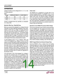
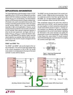
Filter components mutual to the sense lines should be
placed close to the LTC3787, and the sense lines should
run close together to a Kelvin connection underneath the
current sense element (shown in Figure 1). Sensing cur-
rent elsewhere can effectively add parasitic inductance
and capacitance to the current sense element, degrading
the information at the sense terminals and making the
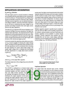
programmed current limit unpredictable. If DCR sensing
is used (Figure 2b), sense resistor R1 should be placed
closetotheswitchingnode,topreventnoisefromcoupling
into sensitive small-signal nodes.
lection of R
(if R
is used) and inductor value.
SENSE
SENSE
Next, the power MOSFETs are selected. Finally, input and
output capacitors are selected. Note that the two control-
ler channels of the LTC3787 should be designed with the
same components.
TO SENSE FILTER,
NEXT TO THE CONTROLLER
+
–
SENSE and SENSE Pins
+
–
The SENSE and SENSE pins are the inputs to the cur-
rent comparators. The common mode input voltage range
of the current comparators is 2.5V to 38V. The current
sense resistor is normally placed at the input of the boost
controller in series with the inductor.
V
IN
INDUCTOR OR R
3787 F01
SENSE
Figure ±. Sense Lines Placement with
Inductor or Sense Resistor
VBIAS
VBIAS
V
V
IN
IN
+
+
SENSE
SENSE
(OPTIONAL)
C1
R2
DCR
L
–
–
SENSE
SENSE
INTV
INTV
CC
CC
INDUCTOR
R1
LTC3787
LTC3787
BOOST
BOOST
TG
TG
V
V
OUT
SW
BG
SW
BG
OUT
SGND
SGND
3787 F02a
3787 F02b
L
DCR
R2
R1 + R2
||
(R1 R2) • C1 =
R
= DCR •
PLACE C1 NEAR SENSE PINS
SENSE(EQ)
(2a) Using a Resistor to Sense Current
(2b) Using the Inductor DCR to Sense Current
Figure 2. Two Different Methods of Sensing Current
3787fc
15

 Linear Systems [ Linear Systems ]