LTC3780
APPLICATIONS INFORMATION
where ∆I is peak-to-peak inductor ripple current. In buck
to handle the maximum RMS current. For buck operation,
the input RMS current is given by:
L
mode, the maximum average load current is:
130mV ΔIL
VOUT
V
IN
V
IN
VOUT
IOUT(MAX,BUCK)
=
+
IRMS ≈IOUT(MAX)
•
•
– 1
RSENSE
2
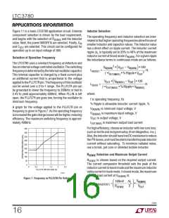
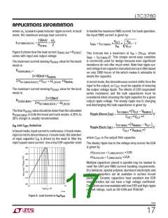
Figure 8 shows how the load current (I
varies with input and output voltage
• R
)
MAXLOAD
SENSE
This formula has a maximum at V = 2V , where
IN
OUT
I
= I
/2. This simple worst-case condition
RMS
OUT(MAX)
is commonly used for design because even significant
deviations do not offer much relief. Note that ripple cur-
rentratingsfromcapacitormanufacturersareoftenbased
on only 2000 hours of life which makes it advisable to
derate the capacitor.
The maximum current sensing R
mode is:
value for the boost
SENSE
RSENSE(MAX)
=
2s160mV sV
IN(MIN)
2sIOUT(MAX,BOOST) sVOUT + ΔIL,BOOST sV
In boost mode, the discontinuous current shifts from the
IN(MIN)
input to the output, so C
must be capable of reducing
OUT
The maximum current sensing R
mode is:
value for the buck
the output voltage ripple. The effects of ESR (equivalent
series resistance) and the bulk capacitance must be
considered when choosing the right capacitor for a given
output ripple voltage. The steady ripple due to charging
and discharging the bulk capacitance is given by:
SENSE
2s130mV
2sIOUT(MAX,BUCK) – ΔIL,BUCK
RSENSE(MAX)
=
The final R
SENSE(MAX)
30% margin is usually recommended.
value should be lower than the calculated
SENSE
IOUT(MAX) • V
– V
IN(MIN)
OUT
(
)
Ripple(Boost,Cap) =
Ripple(Buck,Cap) =
V
V
R
in both the boost and buck modes. A 20% to
COUT • VOUT • f
IOUT(MAX) • VIN(MAX) – V
(
)
OUT
C and C Selection
IN
OUT
COUT • VIN(MAX) • f
In boost mode, input current is continuous. In buck mode,
inputcurrentisdiscontinuous.Inbuckmode,theselection
of input capacitor C is driven by the need to filter the
input square wave current. Use a low ESR capacitor sized
where C
is the output filter capacitor.
OUT
IN
The steady ripple due to the voltage drop across the ESR
is given by:
160
∆V
∆V
= I
• ESR
• ESR
BOOST,ESR
L(MAX,BOOST)
150
140
130
120
110
100
= I
BUCK,ESR
L(MAX,BUCK)
Multiple capacitors placed in parallel may be needed to
meet the ESR and RMS current handling requirements.
Dry tantalum, special polymer, aluminum electrolytic and
ceramic capacitors are all available in surface mount
packages. Ceramic capacitors have excellent low ESR
characteristics but can have a high voltage coefficient.
Capacitors are now available with low ESR and high ripple
current ratings, such as OS-CON and POSCAP.
0.1
1
10
V
/V
(V)
IN OUT
3780 F08
Figure 8. Load Current vs VIN/VOUT
3780fe
17

 Linear Systems [ Linear Systems ]