LTC3780
APPLICATIONS INFORMATION
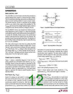
Figure 11 is a basic LTC3780 application circuit. External
component selection is driven by the load requirement,
Inductor Selection
The operating frequency and inductor selection are inter-
relatedinthathigheroperatingfrequenciesallowtheuseof
smaller inductor and capacitor values. The inductor value
has a direct effect on ripple current. The inductor current
and begins with the selection of R
and the inductor
SENSE
value. Next, the power MOSFETs are selected. Finally, C
IN
and C
are selected. This circuit can be configured for
OUT
operation up to an input voltage of 36V.
ripple ∆I is typically set to 20% to 40% of the maximum
L
inductor current at boost mode V
. For a given ripple
IN(MIN)
Selection of Operation Frequency
the inductance terms in continuous mode are as follows:
The LTC3780 uses a constant frequency architecture and
has an internal voltage controlled oscillator. The switching
frequencyisdeterminedbytheinternaloscillatorcapacitor.
This internal capacitor is charged by a fixed current plus
an additional current that is proportional to the voltage
appliedtothePLLFLTRpin.Thefrequencyofthisoscillator
can be varied over a 2-to-1 range. The PLLFLTR pin can
be grounded to lower the frequency to 200kHz or tied to
2.4V to yield approximately 400kHz. When PLLIN is left
open, the PLLFLTR pin goes low, forcing the oscillator to
minimum frequency.
V
2 t V
o V
t100
(
)
IN(MIN)
OUT
IN(MIN)
LBOOST
>
H,
2
ƒ tIOUT(MAX) t ꢀRipple t VOUT
VOUT t VIN(MAX) o VOUT t100
(
)
LBUCK
>
H
ƒ tIOUT(MAX) t ꢀRipple t V
IN(MAX)
where:
f is operating frequency, Hz
% Ripple is allowable inductor current ripple, %
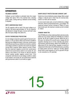
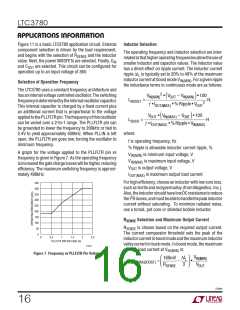
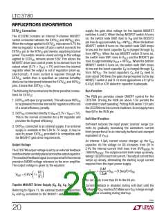
A graph for the voltage applied to the PLLFLTR pin vs
frequency is given in Figure 7. As the operating frequency
isincreasedthegatechargelosseswillbehigher, reducing
efficiency. The maximum switching frequency is approxi-
mately 400kHz.
V
V
V
I
is minimum input voltage, V
is maximum input voltage, V
is output voltage, V
IN(MIN)
IN(MAX)
OUT
is maximum output load current
OUT(MAX)
For high efficiency, choose an inductor with low core loss,
such as ferrite and molypermalloy (from Magnetics, Inc.).
Also,theinductorshouldhavelowDCresistancetoreduce
450
400
350
300
250
200
150
100
50
2
theI Rlosses,andmustbeabletohandlethepeakinductor
current without saturating. To minimize radiated noise,
use a toroid, pot core or shielded bobbin inductor.
R
SENSE
Selection and Maximum Output Current
R
SENSE
is chosen based on the required output current.
The current comparator threshold sets the peak of the
inductorcurrentinboostmodeandthemaximuminductor
valleycurrentinbuckmode. Inboostmode, themaximum
0
0
2
2.5
0.5
1
1.5
PLLFLTR PIN VOLTAGE (V)
3780 F07
average load current at V
is:
IN(MIN)
Figure 7. Frequency vs PLLFLTR Pin Voltage
V
⎛
⎞
ΔIL
2
160mV
IN(MIN)
IOUT(MAX,BOOST)
=
n
s
⎜
⎟
R
VOUT
⎝
⎠
SENSE
3780fe
16

 Linear Systems [ Linear Systems ]