LTC3780
OPERATION
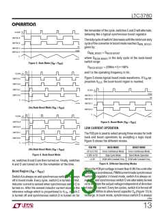
the remainder of the cycle. switches C and D will alternate,
behaving like a typical synchronous boost regulator.
CLOCK
SWITCH A
SWITCH B
ThedutycycleofswitchCdecreasesuntiltheminimumduty
cycle of the converter in boost mode reaches D
given by:
,
MIN_BOOST
0V
SWITCH C
SWITCH D
HIGH
D
= D
MIN_BOOST
BUCK-BOOST
I
L
where D
is the duty cycle of the buck-boost
3780 F03
BUCK-BOOST
switch range:
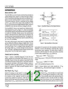
Figure 3. Buck Mode (VIN > VOUT
)
D
= (200ns • f) • 100%
BUCK-BOOST
and f is the operating frequency in Hz.
CLOCK
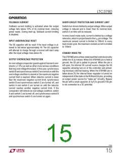
Figure 5 shows typical boost mode waveforms. If V ap-
SWITCH A
IN
proaches V , the buck-boost region is reached.
OUT
SWITCH B
SWITCH C
SWITCH D
CLOCK
HIGH
0V
SWITCH A
SWITCH B
I
L
3780 F04a
SWITCH C
SWITCH D
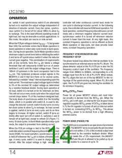
(4a) Buck-Boost Mode (VIN ≥ VOUT
)
I
L
CLOCK
3780 F05
SWITCH A
SWITCH B
Figure 5. Boost Mode (VIN < VOUT
)
LOW CURRENT OPERATION
SWITCH C
SWITCH D
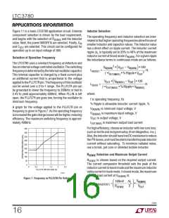
The FCB pin is used to select among three modes for both
buck and boost operations by accepting a logic input.
Figure 6 shows the different modes.
I
L
3780 F04b
FCB PIN
0V to 0.75V
0.85V to 5V
>5.3V
BUCK MODE
BOOST MODE
(4b) Buck-Boost Mode (VIN ≤ VOUT
)
Force Continuous Mode
Skip-Cycle Mode
Force Continuous Mode
Burst Mode Operation
DCM with Constant Freq
Figure 4. Buck-Boost Mode
DCM with Constant Freq
on, switches B and D are then turned on. Finally, switches
A and D are turned on for the remainder of the time.
Figure 6. Different Operating Modes
When the FCB pin voltage is lower than 0.8V, the controller
behavesasacontinuous,PWMcurrentmodesynchronous
switching regulator. In boost mode, switch A is always on.
switch C and synchronous switch D are alternately turned
on to maintain the output voltage independent of direction
of inductor current. Every ten cycles, switch A is forced off
Boost Region (V < V
)
IN
OUT
Switch A is always on and synchronous switch B is always
off in boost mode. Every cycle, switch C is turned on first.
Inductor current is sensed when synchronous switch C is
turned on. After the sensed inductor current exceeds the
reference voltage which is proportional to V , switch C
is turned off and synchronous switch D is turned on for
for about 300ns to allow boost capacitor C (Figure 13) to
A
ITH
recharge. In buck mode, synchronous switch D is always
3780fe
13

 Linear Systems [ Linear Systems ]