LTC3780
OPERATION
MAIN CONTROL LOOP
V
V
OUT
IN
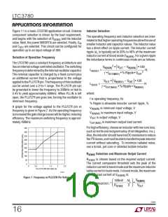
The LTC3780 is a current mode controller that provides an
output voltage above, equal to or below the input voltage.
TheLTCproprietarytopologyandcontrolarchitectureem-
ploys a current-sensing resistor in buck or boost modes.
The sensed inductor current is controlled by the voltage
TG2
BG2
A
D
TG1
BG1
L
SW2
SW1
B
C
R
SENSE
on the I pin, which is the output of the amplifier EA. The
TH
3780 F01
V
pin receives the voltage feedback signal, which is
OSENSE
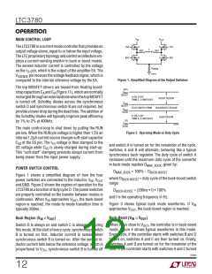
Figure 1. Simplified Diagram of the Output Switches
compared to the internal reference voltage by the EA.
The top MOSFET drivers are biased from floating boost-
strapcapacitorsC andC (Figure11), whicharenormally
98%
MAX
BOOST
D
A
B
A ON, B OFF
rechargedthroughanexternaldiodewhenthetopMOSFET
is turned off. Schottky diodes across the synchronous
switch D and synchronous switch B are not required, but
provide a lower drop during the dead time. The addition of
the Schottky diodes will typically improve peak efficiency
by 1% to 2% at 400kHz.
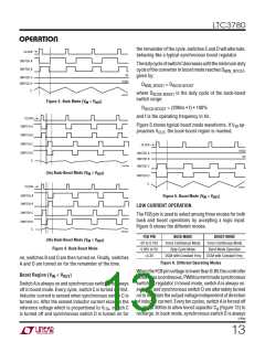
BOOST REGION
PWM C, D SWITCHES
D
MIN
BOOST
FOUR SWITCH PWM
BUCK/BOOST REGION
BUCK REGION
D
MAX
BUCK
D ON, C OFF
PWM A, B SWITCHES
3%
MIN
BUCK
D
3780 F02
The main control loop is shut down by pulling the RUN
pin low. When the RUN pin voltage is higher than 1.5V, an
internal 1.2μA current source charges soft-start capacitor
Figure 2. Operating Mode vs Duty Cycle
C
at the SS pin. The I voltage is then clamped to the
SS
TH
and switch A is turned on for the remainder of the cycle.
switches A and B will alternate, behaving like a typical
synchronous buck regulator. The duty cycle of switch A
increases until the maximum duty cycle of the converter
SS voltage while C is slowly charged during start-up.
SS
This “soft-start” clamping prevents abrupt current from
being drawn from the input power supply.
in buck mode reaches D , given by:
MAX_BUCK
POWER SWITCH CONTROL
D
= 100% – D
BUCK-BOOST
MAX_BUCK
Figure 1 shows a simplified diagram of how the four
where D
range:
= duty cycle of the buck-boost switch
BUCK-BOOST
power switches are connected to the inductor, V , V
IN OUT
and GND. Figure 2 shows the regions of operation for the
LTC3780asafunctionofdutycycleD. Thepowerswitches
are properly controlled so the transfer between modes is
D
= (200ns • f) • 100%
BUCK-BOOST
and f is the operating frequency in Hz.
continuous. When V approaches V , the buck-boost
IN
OUT
Figure 3 shows typical buck mode waveforms. If V
region is reached; the mode-to-mode transition time is
IN
approaches V , the buck-boost region is reached.
typically 200ns.
OUT
Buck-Boost (V ≅ V
)
Buck Region (V > V
)
IN
OUT
IN
OUT
When V is close to V , the controller is in buck-boost
Switch D is always on and switch C is always off during
this mode. At the start of every cycle, synchronous switch
B is turned on first. Inductor current is sensed when
synchronous switch B is turned on. After the sensed in-
ductor current falls below the reference voltage, which is
IN
OUT
mode. Figure 4 shows typical waveforms in this mode.
Every cycle, if the controller starts with switches B and D
turned on, switches A and C are then turned on. Finally,
switches A and D are turned on for the remainder of the
time. If the controller starts with switches A and C turned
proportional to V , synchronous switch B is turned off
ITH
3780fe
12

 Linear Systems [ Linear Systems ]