18
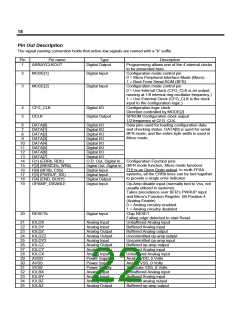
Pin Out Description
The signal naming convention holds that active low signals are named with a “b” suffix.
Pin
1
Pin name
Type
Description
ARRAYCLKOUT
Digital Output
Programming allows one of the 4 internal clocks
to be presented here.
2
MODE[1]
Digital Input
Configuration mode control pin
0 = Micro Peripheral Interface Mode (Micro)
1 = Boot From Serial ROM (BFR)
Configuration mode control pin
3
MODE[2]
Digital Input
0 = Use Internal Clock (CFG_CLK is an output,
running at 1/8 internal ring oscillator frequency.)
1 = Use External Clock (CFG_CLK is the clock
input to the configuration logic.)
4
5
CFG_CLK
DCLK
Digital I/O
Configuration logic clock
Direction controlled by MODE[2]
Digital Output
SPROM Configuration clock output
1/2 frequency of CFG_CLK.
6
DATA[0]
Digital I/O
Data pins used for loading configuration data
and checking status. DATA[0] is used for serial
BFR mode, and the entire byte width is used in
Micro mode.
7
DATA[1]
Digital I/O
8
DATA[2]
Digital I/O
9
DATA[3]
Digital I/O
10
11
12
13
14
15
16
17
18
19
DATA[4]
Digital I/O
DATA[5]
Digital I/O
DATA[6]
Digital I/O
DATA[7]
Digital I/O
F[1] (ERRb, RDb)
F[2] (MEMCEb, WRb)
F[0] (BFRb, CSb)
F[3] (PWRUP, RS)
F[4] (END, BUSY)
OPAMP_DISABLE
O.D. Out, Digital In
Digital Out, Digital In
Digital Input
Digital Input
Digital Output
Digital Input
Configuration Function pins
(BFR mode function, Micro mode function)
F[1] is an Open Drain output. In multi-FPAA
systems, all the ERRb lines can be tied together
to provide a single error indicator.
Op-Amp disable input (normally tied to Vss, not
usually utilized in systems)
Takes precedence over BFR’s PWRUP input
and Micro’s Function Register Bit Position 4
(Analog Enable)
0 = Analog circuitry enabled
1 = Analog circuitry disabled
Chip RESET
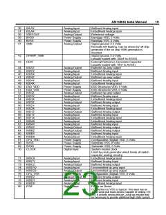
20
RESETb
Digital Input
Falling edge detected to start Reset
Unbuffered Analog input
Buffered Analog input
21
22
23
24
25
26
27
28
29
30
31
32
33
34
35
IOLDX
IOLDY
IOLDZ
IOLDZ2
IOLDY2
IOLCZ
IOLCY
IOLCX
AVDD
AVSS
Analog Input
Analog Input
Analog Output
Analog Output
Analog Input
Analog Output
Analog Input
Analog Input
Power Supply
Power Supply
Power Supply
Analog Input
Analog Input
Analog Output
Analog Output
Buffered Analog output
Uncommitted op-amp output
Uncommitted op-amp input
Buffered op-amp output
Buffered Analog input
Unbuffered Analog input
Analog VDD, 5 Volts
Analog VSS, 0 Volts
SVSS
Substrate VSS, 0 Volts
IOLBX
IOLBY
IOLBZ
IOLAZ
Unbuffered Analog input
Buffered Analog input
Buffered analog output
Buffered op-amp output

 LATTICE [ LATTICE SEMICONDUCTOR ]