16
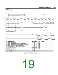
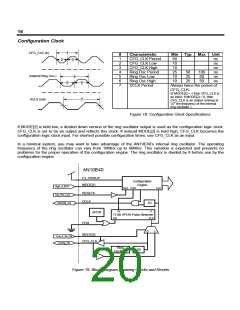
Configuration Clock
CFG_CLK (in)
2
1
5
#
1
2
3
4
5
6
7
Characteristic
CFG_CLK Period
CFG_CLK Low
CFG_CLK High
Ring Osc Period
Ring Osc Low
Ring Osc High
DCLK Period
Min
50
10
10
25
10
10
Typ
Max
Unit
ns
3
ns
ns
50
25
25
100
50
ns
(Internal Ring Osc.)
DCLK (out)
4
ns
50
ns
6
7
Always twice the period of
CFG_CLK.
(If MODE[2] = 1 then CFG_CLK is
an input. If MODE[2] = 0, then
CFG_CLK is an output running at
1
/
th the frequency of the internal
8
ring oscillator.)
Figure 18. Configuration Clock Specifications
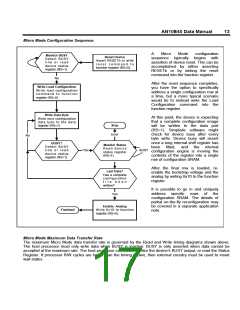
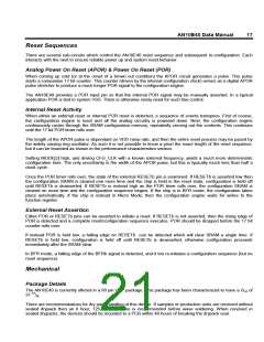
If MODE[2] is held low, a divided down version of the ring oscillator output is used as the configuration logic clock.
CFG_CLK is set to be an output and reflects this clock. If instead MODE[2] is held high, CFG_CLK becomes the
configuration logic clock input. For shortest possible configuration times, use CFG_CLK as an input.
In a minimal system, you may want to take advantage of the AN10E40’s internal ring oscillator. The operating
frequency of the ring oscillator can vary from 10MHz up to 40MHz. This variation is expected and presents no
problems for the proper operation of the configuration engine. The ring oscillator is divided by 8 before use by the
configuration engine.
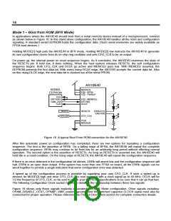
AN10E40
F3, PWRUP
Configuration
MODE[1]
RESETb
DCLK
Engine
High_4_BFR
Sys_Rst_Low
SPROM_Clk
RST POR
CLK
1/2
16
0
APOR
17 Bit APOR Pulse Stretcher
EN
CLK
POR
0
1
MODE[2]
Low_4_Int_Clk
Config_Clk
CFG_CLK
Ring
Oscillator
1/8
Figure 19. Block Diagram Showing Clocks and Resets

 LATTICE [ LATTICE SEMICONDUCTOR ]