ISL6366
channel and the output rail; DON’T place it close to the MOSFET
side, which generates much more heat.
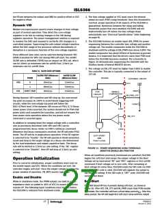
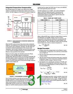
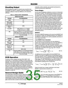
Integrated Temperature Compensation
The ISL6366 utilizes the voltage at the TM pin and “TCOMP”
register to compensate the temperature impact on the sensed
current. The block diagram of this function is shown in Figure 22.
ISL6366 multiplexes the “TCOMP” value with the TM digital
signal to obtain the adjustment gain to compensate the
temperature impact on the sensed channel current. The
compensated channel current signal is used for droop and
overcurrent protection functions.
VCC
Isen4
Isen3
Isen2
Isen1
ISL6366
TABLE 8. “TCOMP” AND “TCOMPS” VALUES
CHANNEL
CURRENT
SENSE
RTM
TCOMP/TCOMPS (°C)
TCOMP/TCOMPS (°C)
NON-LINEAR
A/D
TM
13
16
29.7
32.4
35.1
37.8
40.5
43.2
OFF
I4
I3
I2
I1
oc
RNTC
18.9
21.6
24.3
27
ki
D/A
PLACE NTC
CLOSE TO
CHANNLE 1
4-BIT
A/D
DROOP AND
OVERCURRENT
PROTECTION
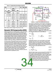
When a different NTC type or different voltage divider is used for
the TM function, the TCOMP voltage can also be used to
compensate for the difference between the recommended TM
voltage curve in Figure 20 and that of the actual design. If the
same type NTC (β = 3477) but different value is used, the pull-up
resistor needs to be scaled, as shown in Equation 22:
TCOMP
FIGURE 22. BLOCK DIAGRAM OF INTEGRATED TEMPERATURE
COMPENSATION
When the NTC is placed close to the current sense component
(inductor), the temperature of the NTC will track the temperature
of the current sense component. Therefore, the TM voltage can
be utilized to obtain the temperature of the current sense
component. Since the NTC could pick up noise from phase node,
a 0.1µF ceramic decoupling capacitor is recommended on the
TM pin in close proximity to the controller.
1kΩ ⋅ R
NTC_NEW
(EQ. 22)
R
= -------------------------------------------
TM
6.8kΩ
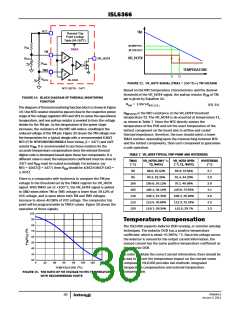
Design Procedure
1. Properly choose the voltage divider for the TM pin to match
the TM voltage vs temperature curve with the recommended
curve in Figure 20.
Based on the VCC voltage, the ISL6366 converts the TM pin
voltage to a 6-bit TM digital signal for temperature
2. Run the actual board under the full load and the desired
cooling condition.
compensation. With the non-linear A/D converter of ISL6366, the
TM digital signal is linearly proportional to the NTC temperature.
For accurate temperature compensation, the ratio of the TM
voltage to the NTC temperature of the practical design should be
similar to that in Figure 20.
3. After the board reaches the thermal steady state, record the
temperature (T
) of the current sense component (inductor
CSC
or MOSFET) and the voltage at TM and VCC pins.
4. Use Equation 23 to calculate the resistance of the NTC, and
find out the corresponding NTC temperature T
from the
NTC
NTC datasheet or using Equation 24, where β is equal to 3477
for recommended NTC.
V
xR
OUTPUT
PHASE1
TM
TM
(EQ. 23)
(EQ. 24)
R
(T
) = -------------------------
NTC NTC
V
– V
INDUCTOR
VOUT
POWER
STAGE
CC
TM
β
--------------------------------------------------------------------
T
=
– 273.15
NTC
RTM
β
⎛
⎞
NTC
-------------------------------
------------------
ln
+
⎝
⎠
R
(T
)
298.15
NTC NTC
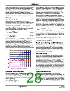
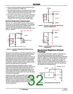
FIGURE 23. RECOMMENDED PLACEMENT OF NTC
5. In Intersil designed worksheet, choose a number close to the
result as in Equation 25 in the “TCOMP” cell to calculate the
needed resistor network for the register “TCOMP” pin. (Note:
for worksheet, please contact Intersil Application support at
www.intersil.com/design/).
Since the NTC attaches to the PCB, but not directly to the current
sensing component, it inherits high thermal impedance between
the NTC and the current sensing element. The “TCOMP” register
values can be utilized to correct the temperature difference
between NTC and the current sense component. As shown in
Figure 23, the NTC should be placed in proximity to the PSI
(EQ. 25)
T
= T
– T
CSC NTC
COMP
FN6964.0
January 3, 2011
31

 INTERSIL [ Intersil ]